Installation
MP150 Rev. E3 07/2013 29
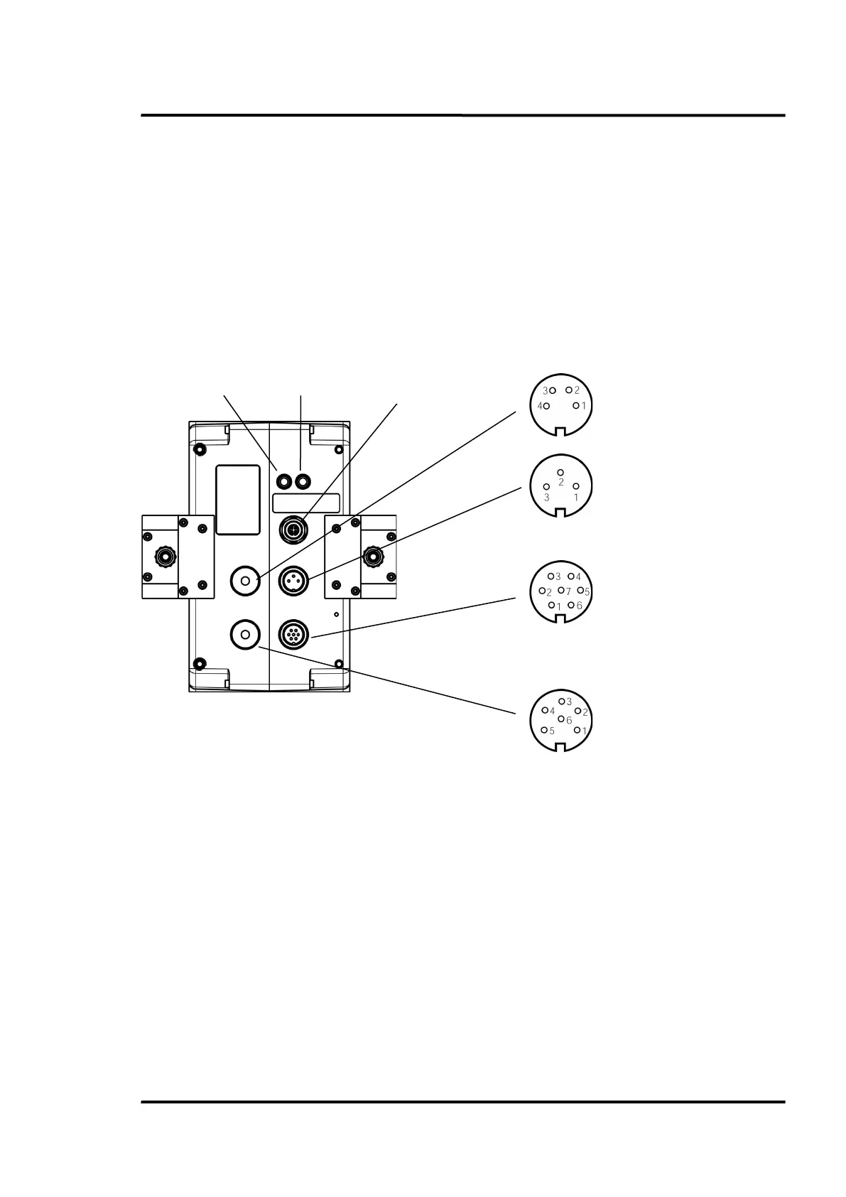
5.11 Input and Output Connectors
In addition to the communication interfaces, the linescanner is also equipped with the following:
• three active analog current outputs
• an alarm output (potential-free relay contacts)
• a trigger input for synchronization
The housing of the linescanner is electrically grounded. All inputs and outputs are electrically isolated
from the housing, the input voltage, and from one another. The current outputs have a joint ground
connection, but are electrically isolated from any other ground connection.
Figure 11: Input and Output Connectors (view on connectors)
IGND
OUT 1
OUT 2
OUT 3
GND
n.c.
+24 VDC
GND
T+
T-
R+
R-
n.c.
12 VDC
Relay contact
Relay contact
Trigger + 5 to 24 VDC
Trigger GND
Functional Input: max. + 5 VDC
Functional Input: GND
 Loading...