Accessories
MP150 Rev. E3 07/2013 51
7.10 Alarm Module
The system can accommodate an Alarm Module to allow the output of one digital alarm signal and the
input of a trigger signal to:
• inhibit or stop the measurement,
• automate the saving of the current snapshot.
For configuring of the Alarm Module see the <Input/Output> page of the Software Configurator. The
Alarm Module cannot not be used to trigger snapshots.
The alarm output (24 VDC) is high active meaning each alarm provides a voltage of 24 VDC on the
output.
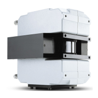
Figure 30: Connection to the PC
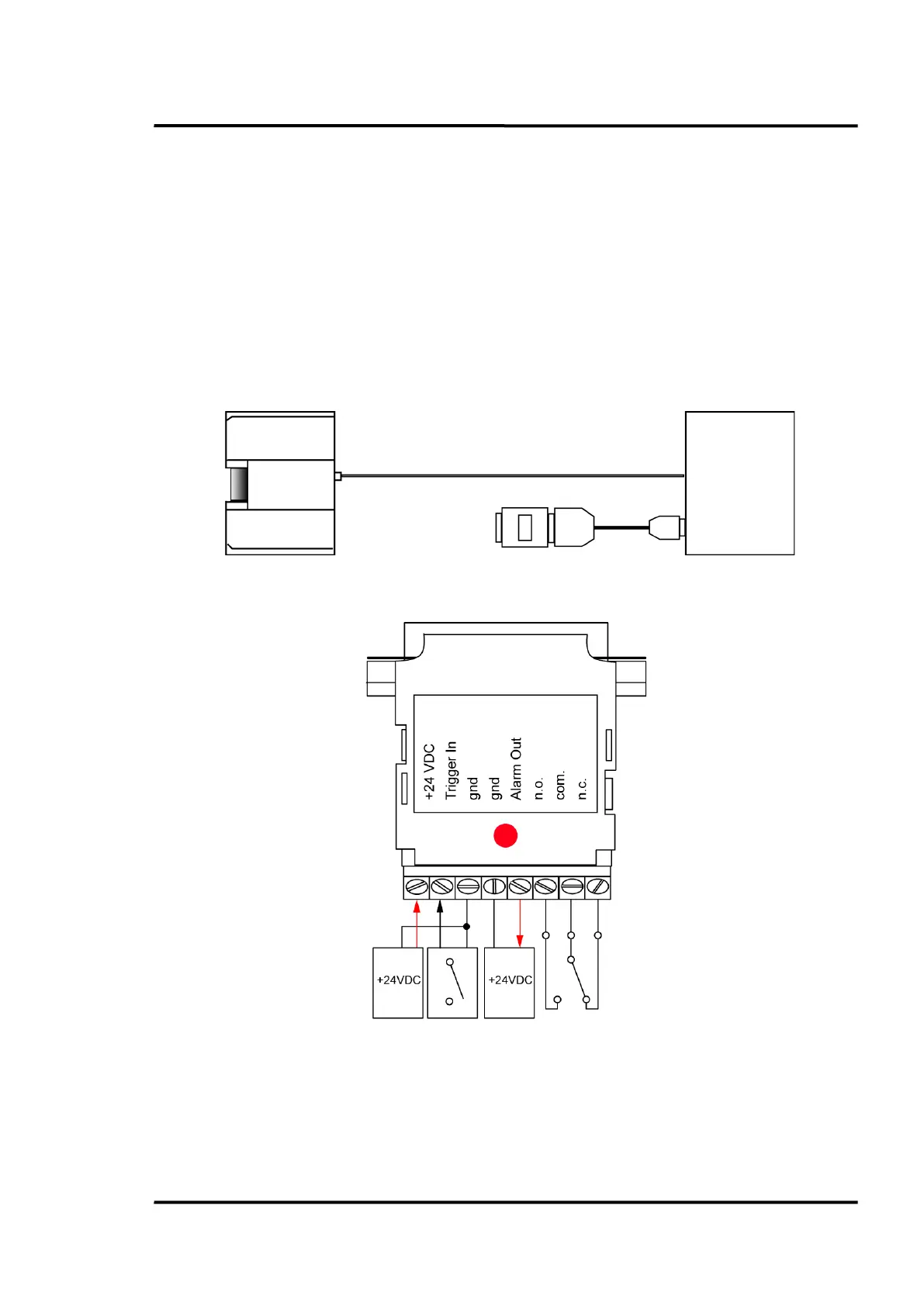
Figure 31: Wiring
Out
24 VDC /
1 A
Out
Contacts
30 V / 1 A
In
Closing
Contact
Supply
24 VDC
 Loading...