T-one ULS
Rev. 06/18 12/26
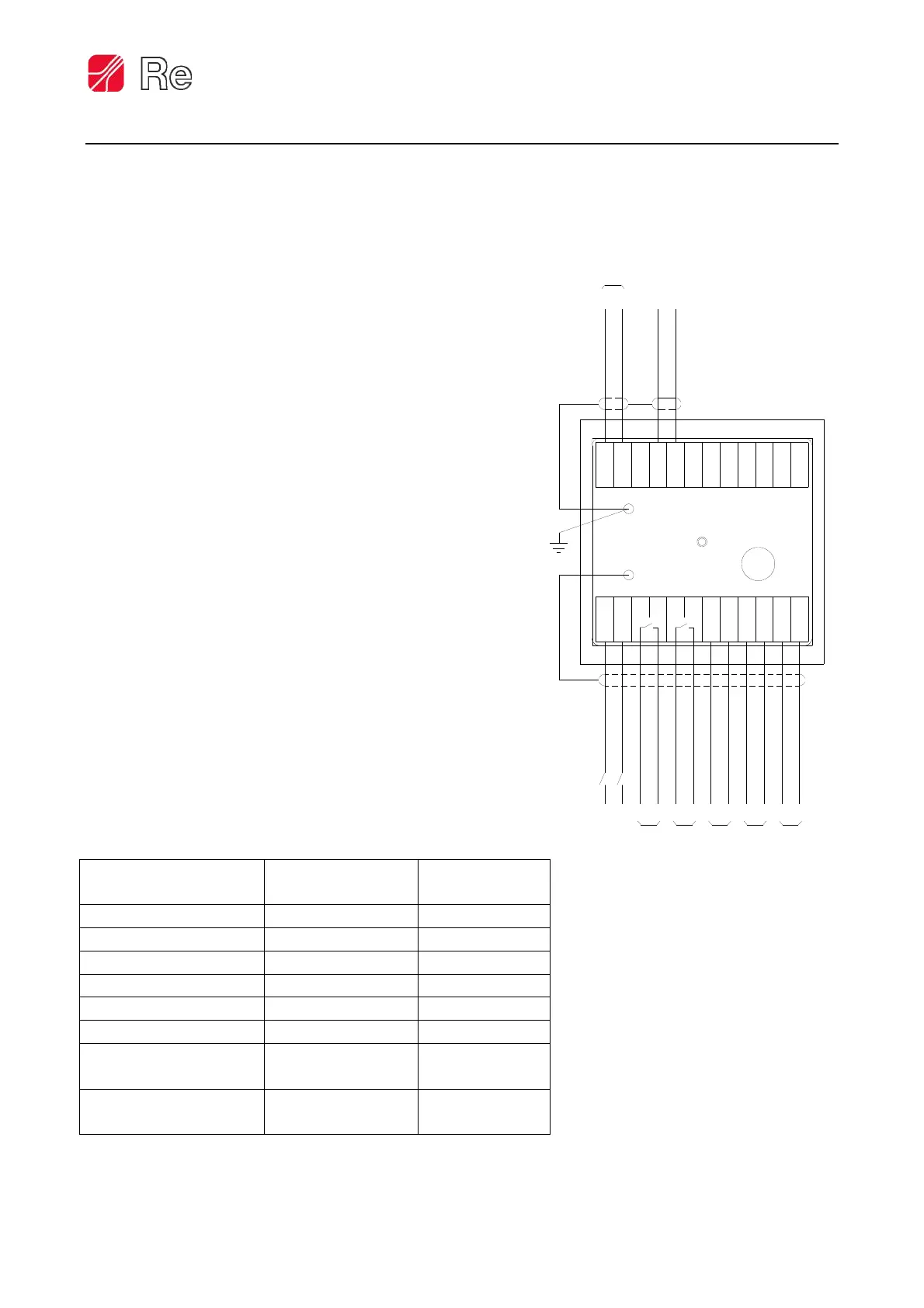
Electrical connection diagrams
Inputs / Outputs Type
Electrical
characteristics
AIN0 Analog input 4÷20mA
AIN1 Analog input 0÷10Vdc
Auto/Stop Digital input 0÷24Vdc
Priority stop Digital input 0÷24Vdc
Brake control output Analog output 0÷10Vdc
Prop. diameter output Analog output 0÷10Vdc
ALL.0 Digital output Relay 24Vdc
750mA max
ALL.1 Digital output Relay 24Vdc
750mA max
The instrument must be connected to the
zero potential by using the screw located
close to the CN1 contact
The connection to ground must be
as short as possible
16
ALL.0
1513 14
Power supply
2
1
4
3
NC
+ -
Analog output
Brake control analog output
AIN1
ALL.1
- +
- + - +
242319 20 21 22
17 18
965871110 12
NC
NC
NC
NC
NC
NC
0V
AIN0
+ -
DIN0 (Auto/Stop)
DIN1 (Priority stop)
(proportional to the diameter)
CN1
CN2
 Loading...