Do you have a question about the Re T-one ULS and is the answer not in the manual?
| Brand | Re |
|---|---|
| Model | T-one ULS |
| Category | Controller |
| Language | English |
Information on device recovery, EU and non-EU disposal guidelines.
How the taper tension function operates on rewinders.
How the taper tension function operates on unwinders.
Torque percentages developed by different caliper colors.
Guidelines for assigning calipers to braking sections.
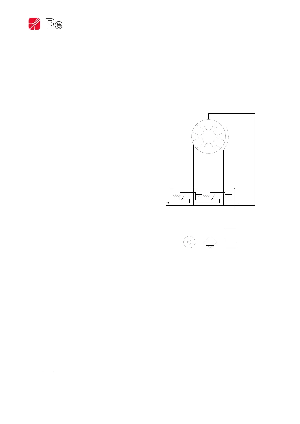
Pneumatic and electrical connections for Selematic function.
Details of the instrument's front panel display.
Explanation of the IN and OUT bar graph displays.
Steps for physically installing the T-one ULS regulator.
How to enter the adjustment mode for calibration.
Calibration for diameter input and settings (F.30-F.33).
Voltage and connection requirements for the instrument's power supply.
Description of AUTO/STOP and PRIORITY STOP digital inputs.
Description of Alarm 0, Alarm 1, EV.0, and EV.1 digital outputs.
Characteristics and usage of the AINO analog input.
Description of the analog output proportional to the diameter.
Configuration options for the analog output signal.
Setting brake/clutch or motor usage when the machine is stationary.
Setting tension variation percentage when the machine is stopped.
Setting or checking the programming password.
Procedure to access the instrument calibration.
Setting brake/clutch usage during PRIORITY STOP state.
Setting the taper percentage for diameter-based tension adjustment.
Setting the diameter where taper function becomes active.
Setting the diameter for taper function subtraction/addition.
Setting minimum braking percentage in AUTO state.
Setting time interval for acceleration phase.
Setting inertia contribution during acceleration.
Setting time interval for deceleration phase.
Setting inertia contribution during deceleration.
Configuring how the instrument signals alarm thresholds.
Setting the diameter value for the first alarm signal.
Setting the diameter value for the second alarm signal.
Enabling or disabling alarm visualization on the display.
Setting the analog input for diameter reference acquisition.
Setting the decimal point position for diameter display.
Setting the maximum diameter value for reel working.
Acquiring the maximum diameter analog reference from the sensor.
Setting the minimum diameter value for reel working.
Acquiring the minimum diameter analog reference from the sensor.
Activating tension set point control via analog signal.
Setting the minimum analog signal for remote set point.
Setting the maximum analog signal for remote set point.
Setting AUTO/STOP control via keypad or remote contact.
Setting the percentage for the first braking section (SECT.1).
Setting the percentage for the second braking section (SECT.2).
Setting the percentage for the third braking section (SECT.3).
Setting the output type for brake/clutch or motor control.
Adjusting the display update speed by filtering values.
Eliminating interference on AINO and AIN1 analog inputs.
Setting a password to prevent unauthorized programming.
Resetting all functions to their factory default settings.
Regulating the brightness level of the instrument display.
Viewing the device's firmware version.
Details on analog inputs and outputs for the device.
Details on digital inputs and outputs for the device.
Power supply, weight, temperature, and protection ratings.
Dimensions and requirements for the instrument's mounting hole.