T-one ULS
Rev. 06/18 5/26
How to set the “Selematic” work mode
Perform these settings by following the order set out.
1. Enter in function F.50 the calipers percentages total in SECT.1 (in the example 16%)
2. Enter in function F.51 the calipers percentages total in SECT.2 (in the example 40%)
3. Enter in function F.52 the calipers percentages total in SECT.3 (in the example 140%)
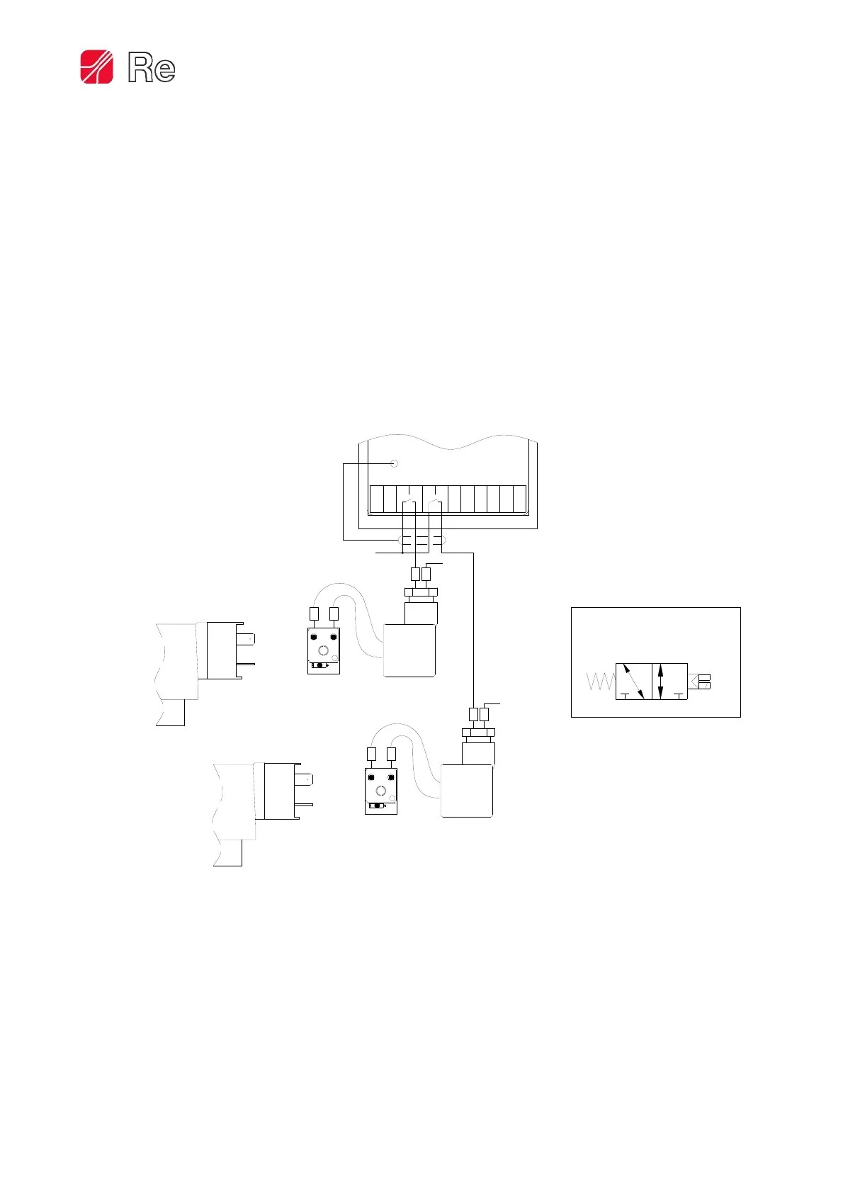
Pneumatic and electrical connection of the electro valves
The pneumatic and electrical connection is shown in the figure below.
For the correct operation of the system, follow the pneumatic connection of the electro valve EV.0 to the
SECT.2, and the electro valve EV.1 to the SECT.3 as shown in the previous page. The air path between the
electro valves and the brake caliper must be as short as possible.
1
2
12
0V
1 2
Electro valve
connector
rear view
EV.0
1
2
12
1 2
Electo valve
connector
rear view
EV.1
0V
RP
A
CONNECTOR E.V. FORM B IND. PROTECT. CIRCUIT
(Code Re E0304072)
*
*
Electro valve
pneumatic symbols
*
13 242321 2220191817161514
CN2 T-One
24Vdc
 Loading...