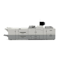
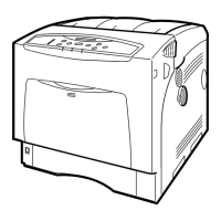
Exterior: Rear View
11
1
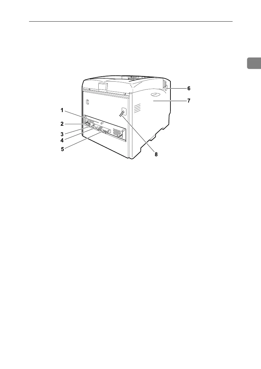
Exterior: Rear View
1. Controller Board
Slide this out to install options such as the
memory unit, user account enhance unit
or printer hard disk. Plug cables such as
the USB cable and Ethernet cable into
their connectors.
2. Ethernet Port
Use a network interface cable to connect
the printer to the network.
3. USB Port
Use a USB cable to connect the printer to
the host computer.
4. Optional Interface Board Slots
Insert an optional 1394 interface board,
802.11b interface unit, wireless interface
board, or 1284 interface board in this slot.
Up to two interface board can be inserted
at a time.
5. Expansion Card Slots
Install expansion cards in these slots.
There are three slots.
When you use the expansion card, use
the centre slot.
6. Front Cover (A) Open Levers
7. Left Cover
Open this cover when replacing the pho-
to conductor unit (PCU), intermediate
transfer unit or waste toner cartridge.
8. Power Cable
AET002S
GaiaP1GB_Setup-F4_FM_forPaper.book Page 11 Friday, June 3, 2005 7:50 AM
 Loading...