Chapter 3 Performance Test RIGOL
Service Guide for DS1000E, DS1000D Series
Logic Analyzer Interface Test (Only for DS1000D Series)
Purpose:
Test if the Logic Analyzer (hereinafter referred to as LA) interface works normally
through the logic signal output module (DG-POD-A) of DG3000.
Tools:
A set of DS1000D series digital oscilloscope
A set of DG3000 Function/ Arbitrary waveform Generator
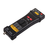
An active logic head
Two logic cables
17 logic testing leads
A DG-POD-A module
Steps:
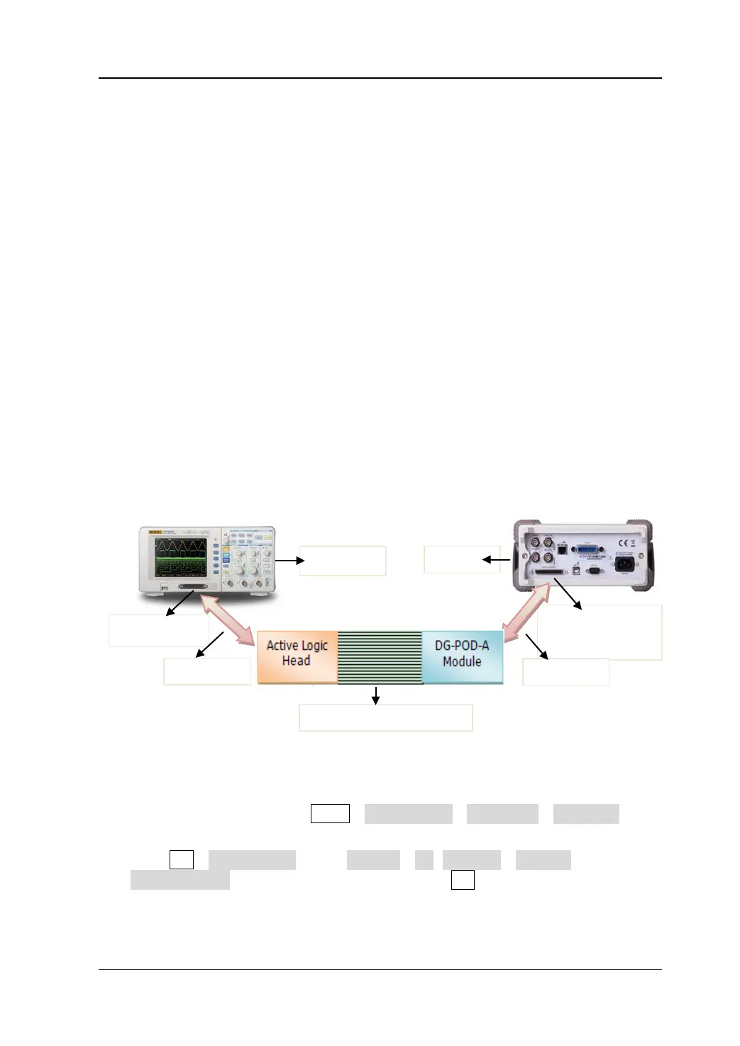
1. Connect LA interface on DS1000D with the active logic head by logic cable.
2. Connect “DIGITAL OUTPUT” interface on the rear panel of DG3000 with
DG-POD-A module by logic cable.
3. Connect the active logic head with DG-POD-A module by logic testing leads, so as
to realize DS1000D and DG3000 connection.
Figure 3-11 DS1000D LA interface connection
4. Power on DS1000D and DG3000 respectively.
5. Turn on DG3000 and press Utility→Output Setup→Digit-Modu→Power on to
enable the digital module power on.
6. Press Arb→Edit Digital W, select Protocol→PO, Code Pat→ 32PRBS and adjust
Output Length as 16 Byte as follows, then press Arb button to output digital
signal.
Interface
 Loading...