Chapter 3 Performance Test RIGOL
Service Guide for DS1000E, DS1000D Series
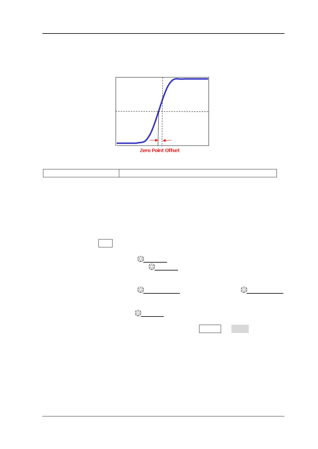
Zero Point Offset Test
Zero point offset is defined as the offset of the crossing point of the waveform and the
trigger level relative to the trigger position as shown in the figure below.
Specification:
Test Devices: Fluke 9500B
Test Procedures:
1) Connect the active head of Fluke 9500B to CH1 of the oscilloscope.
2) Output a fast edge signal with 150 ps rise time and 600 mV amplitude from
Fluke 9500B.
3) Configure the oscilloscope:
a) Press CH1 in the vertical control area (VERTICAL) at the front panel to
enable CH1.
b) Rotate VERTICAL SCALE to set the vertical scale to 100 mV/div.
c) Rotate HORIZONTAL SCALE to set the horizontal time base to 2
ns (for 50 MHz bandwidth oscilloscopes, set the horizontal time base to
5 ns).
d) Rotate VERTICAL POSITION and HORIZONTAL POSITION
to set the vertical position and horizontal position to appropriate values
respectively.
e) Rotate TRIGGER LEVEL to adjust the trigger level to the middle of
the screen.
4) Observe the display of the oscilloscope. Press Cursor Mode “Manual”
to enable the manual cursor function to measure the zero point offset and
record the measurement result.
5) Keep other settings unchanged and adjust the amplitude of the fast edge
signal to 3 V.
6) Set the vertical scale to 500 mV/div. Measure the zero point offset according
to the above method and record the test result.
7) Turn CH1 off. Repeat the above test steps to measure CH2 and record the
test results.
 Loading...