Rockwell Automation Publication 1769-IN088A-EN-P - February 2011 129
I/O Memory Mapping Chapter 3
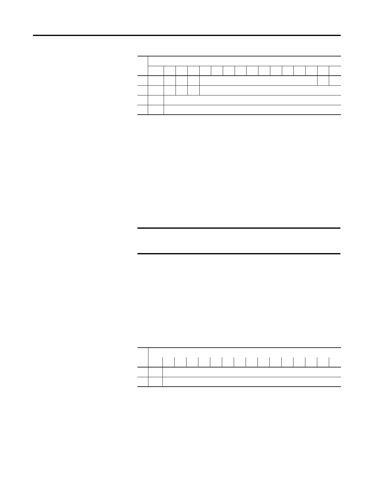
The bit definitions are as follows:
• Dx = Diagnostic bits. When set, they indicate a broken output wire or
high load resistance (not used on voltage outputs).
• Hx = Hold Last State bits. When set, they indicate that the channel is in a
hold last state condition.
• Sx = General Status bits. When set, these bits indicate an error (over-range,
under-range, or diagnostic bit) associated with that channel or a module
hardware error.
• Ux = Under-range flag bits.
• Ox = Over-range flag bits.
• SGN = Sign bit in two’s complement format.
Output Data File
For each module, slot x, words 0 and 1 in the output data file contain the channel
0 and channel 1 output data.
SGN = Sign bit in two’s complement format.
Word
Bit Position
15 14131211109876543210
0 D0 H0 D1 H1 Not Used (Bits set to 0) S1 S0
1 U0 O0U1O1Bits set to 0
2 SGN Output Data Loopback/Echo Channel 0
3 SGN Output Data Loopback/Echo Channel 1
The output module’s input data file reflects the analog output data echo
of the module, not necessarily the electrical state of the output
terminals. It does not reflect shorted or open outputs.
It is only important to use these input words if the controller supports
the Program mode or Fault mode function, and if it is configured to
use them.
Word
Bit Position
1514131211109876543210
0 SGN Analog Output Data Channel 0
1 SGN Analog Output Data Channel 1

 Loading...


