136 Rockwell Automation Publication 1769-IN088A-EN-P - February 2011
Chapter 3 I/O Memory Mapping
The bits are defined as follows:
• S = General status (over-range, under-range, or low/high clamp exceeded).
• H = Output held bit.
• U = Under-range (or low-clamp exceeded) alarm.
• O = Over-range (or high-clamp exceeded) alarm.
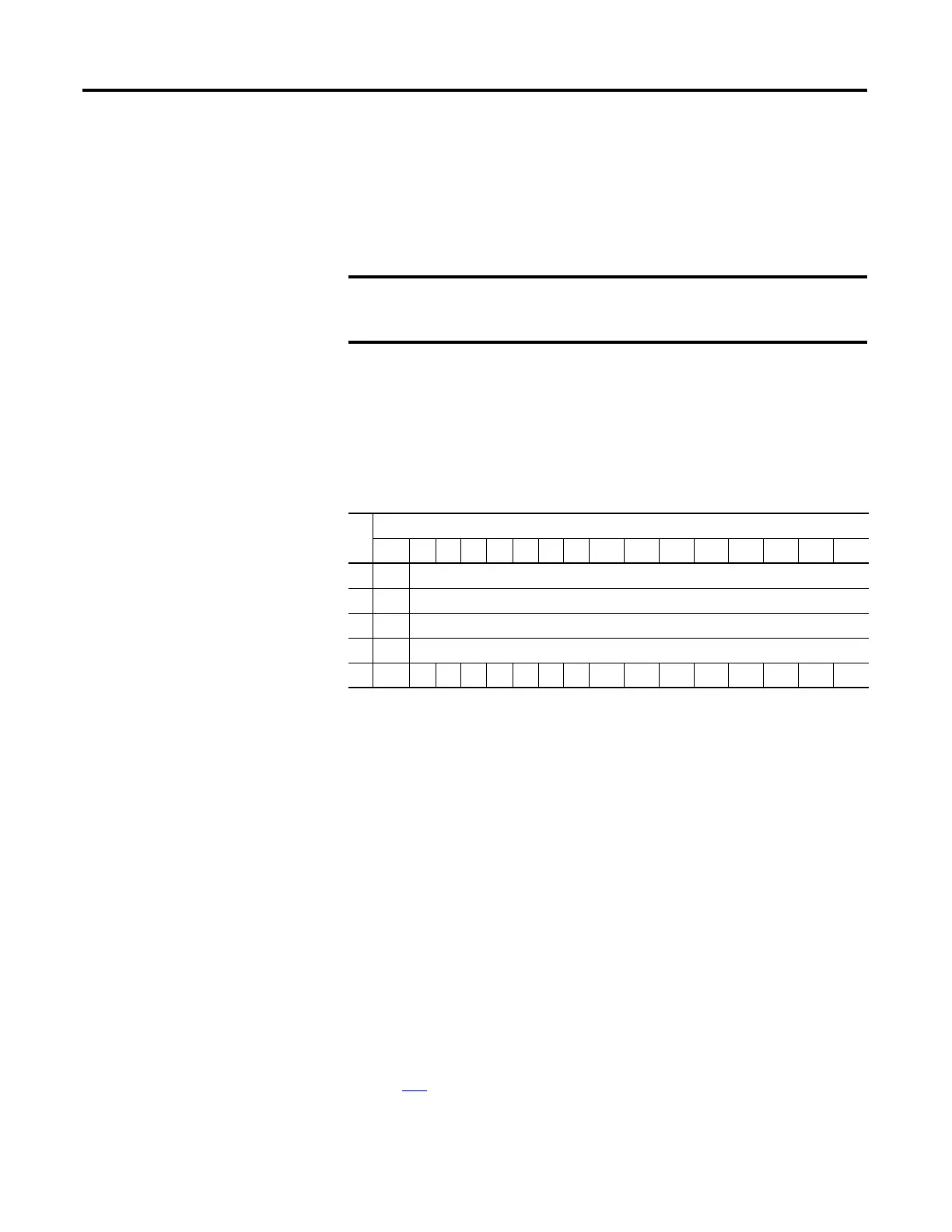
Output Data File
For each module, slot x, words 0…3 in the output data file contain the channel
0…3 output data. Word 4 is used to unlatch any condition that has been latched.
Refer to your module’s user manual for additional details.
The bits are defined as follows:
• SGN = Sign bit in two’s complement format (must be set to 0).
• UU = Unlatch under-range (or low clamp exceeded) alarm.
• UO = Unlatch over-range (or high clamp exceeded) alarm.
Configuration Data File
The manipulation of the bits from this file is normally done with programming
software, such as RSLogix 500, RSLogix 5000, or RSNetWorx for DeviceNet,
during initial configuration of the system. In that case, graphical screens are
provided by the programmer to simplify configuration.
However, some systems, like the 1769-ADN DeviceNet adapter, also allow the
bits to be altered as part of the control program, using communication rungs. In
that case, it is necessary to understand the bit arrangement. The channel
configuration words, the first two words of each eight word group, are described
on page 137
. Refer to your module’s user manual for additional details.
The output module’s input data file reflects the analog output data echo
of the module, not necessarily the electrical state of the output
terminals. It does not reflect shorted or open outputs.
Word
Bit Position
15 14 13 12 11 10 9 8 7 6 5 4 3 2 1 0
0 SGN Analog Output Data Channel 0
1 SGN Analog Output Data Channel 1
2 SGN Analog Output Data Channel 2
3 SGN Analog Output Data Channel 3
4 UU3 UO3 UU2 UO2 UU1 UO1 UU0 UO0

 Loading...


