Rockwell Automation Publication 1769-IN088A-EN-P - February 2011 15
Install a 1769 Module Chapter 1
8. Attach an end-cap terminator (5) to the last module in the system by using
the tongue-and-groove slots as before.
9. Lock the end-cap bus terminator (6).
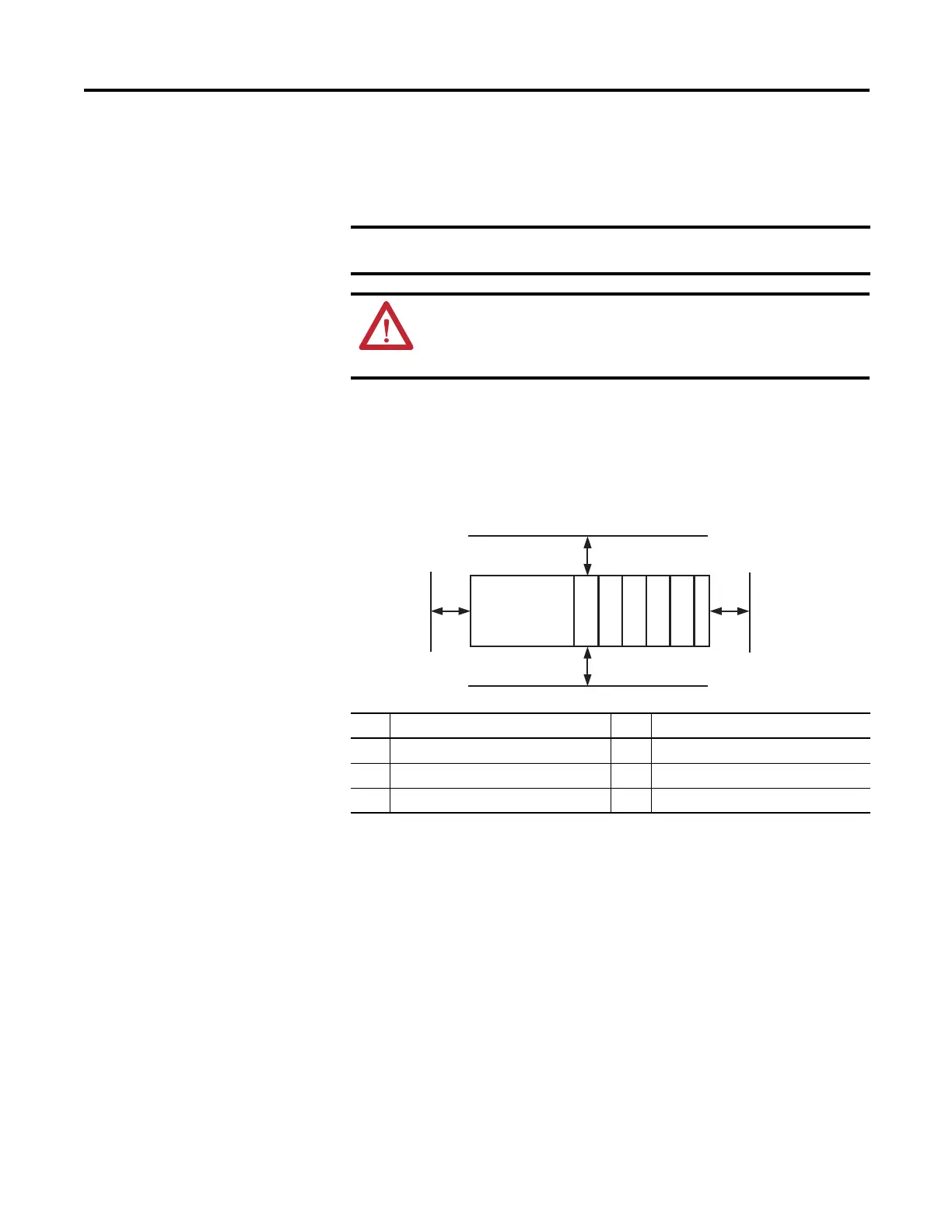
Minimum Spacing
Maintain spacing from enclosure walls, wireways, and adjacent equipment. Allow
50 mm (2 in.) of space on all sides for adequate ventilation.
Panel Mounting
Mount the module to a panel by using two screws per module. Use M4 or #8
panhead screws. Mounting screws are required on every module.
A 1769-ECR or 1769-ECL right or left end cap must be used to terminate
the end of the serial communication bus.
ATTENTION: During panel or DIN rail mounting of all devices, be sure
that all debris, such as metal chips and wire strands, is kept from falling
into the module. Debris that falls into the module could cause damage on
powerup.
Item Description Item Description
1Top 4Side
2 Compact I/O modules 5 Bottom
3 End cap 6 Host controller

 Loading...


