Rockwell Automation Publication 1769-IN088A-EN-P - February 2011 81
I/O Memory Mapping Chapter 3
The bits are defined as follows:
• SGN = Sign bit in 2’s complement format.
• Nu = Not Used. Bit set to 0.
• Sx = General Status bit for input channels 0…15.
• Ox = Over range flag bits for input channels 0…15.
• Ux = Under range flag bits for input channels 0…15.
• Hx = High Alarm flag bits for input channels 0…15.
• Lx = Low Alarm flag bits for input channels 0…15.
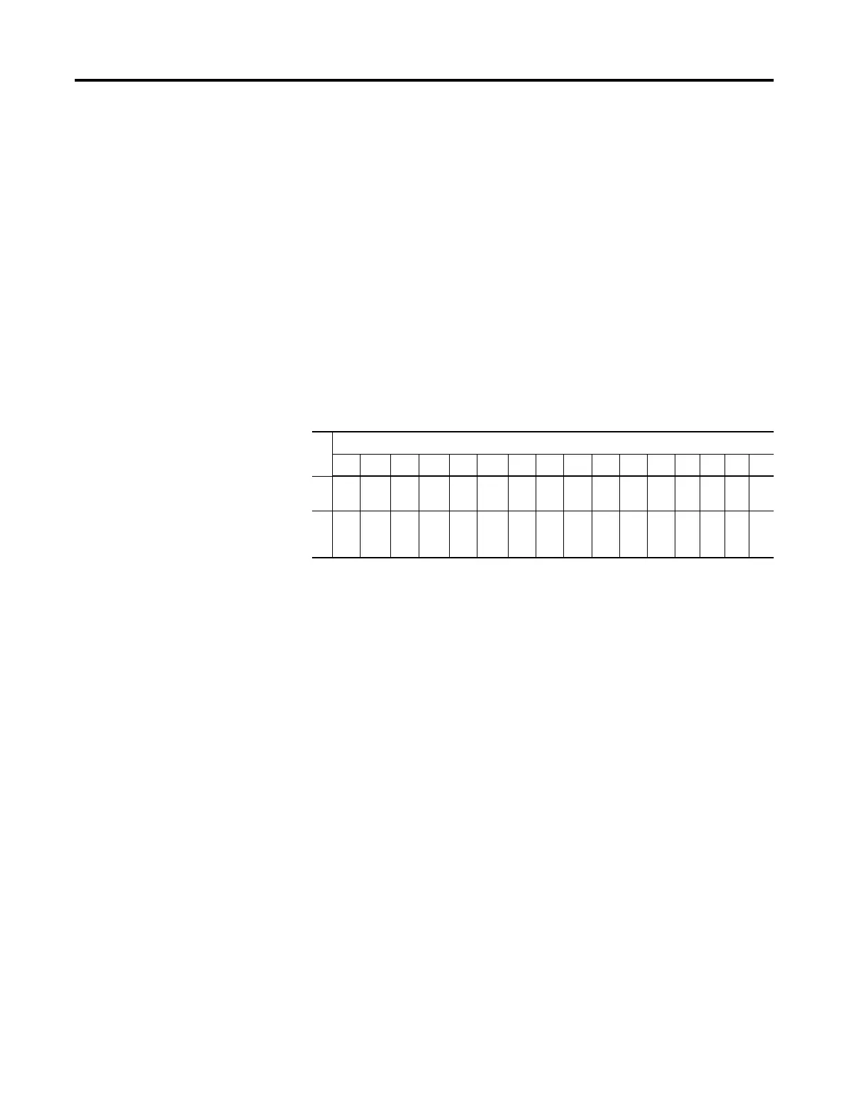
Output Data File
For each module, slot x, words 0 and 1 in the output data file contain the cancel
latched channel alarm control bits.
The bits are defined as follows:
• CLHx = Cancel High Process Alarm Latch for Input x. Allows each input
high-process-alarm latch to be individually cancelled. Cancel = 1.
• CLLx = Cancel Low Process Alarm Latch for Input x. Allows each input
low-process-alarm latch to be individually cancelled. Cancel = 1.
Configuration Data File
The manipulation of bits from this file is normally done with programming
software, such as RSLogix 500, RSLogix 5000, or RSNetWorx for DeviceNet
software, during initial configuration of the system. In that case, graphical screens
provided by the programming software simplify configuration.
Word
Bit Position
15 14 13 12 11 10 09 08 07 06 05 04 03 02 01 00
0CLL
7
CLH
7
CLL
6
CLH
6
CLL
5
CLH
5
CLL
4
CL
H4
CLL
3
CL
H3
CLL
2
CL
H2
CL
L1
CL
H1
CL
L0
CL
H0
1CLL
15
CLH
15
CLL
14
CLH
14
CLL
13
CLH
13
CLL
12
CL
H1
2
CLL
11
CL
H1
1
CLL
10
CL
H1
0
CL
L9
CL
H9
CL
L8
CL
H8

 Loading...


