66 Rockwell Automation Publication 1769-IN088A-EN-P - February 2011
Chapter 3 I/O Memory Mapping
Output Data File
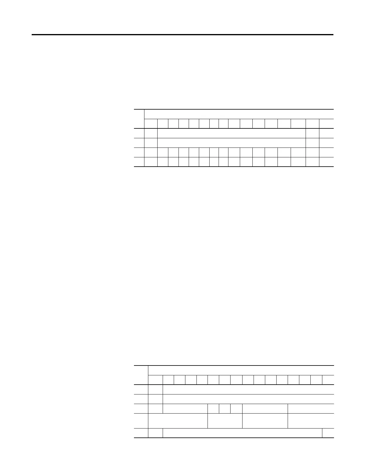
For each module, slot x, words 0 and 1 in the output data file contain the control
program’s directed state of the module’s analog output channels. Word 2 contains
the cancel input channel alarm control bits. Word 3 contains the cancel output
channel clamp control bits.
The bits are defined as follows:
• SGN = Sign bit in 2’s complement format.
• CHIx = Cancel High Process Alarm Latch for Input x. Allows each input
high-process-alarm latch to be individually cancelled. Cancel = 1.
• CLIx = Cancel Low Process Alarm Latch for Input x. Allows each input
low-process-alarm latch to be individually cancelled. Cancel = 1.
• CHOx = Cancel High Clamp Alarm Latch for Output x. Allows each
output high-clamp-alarm latch to be individually cancelled. Cancel = 1.
• CLOx = Cancel Low Clamp Alarm Latch for Output x. Allows each
output low-clamp-alarm-latch to be individually cancelled. Cancel = 1.
Configuration Data File
The manipulation of bits from this file is normally done with programming
software, such as RSLogix 500, RSLogix 5000, or RSNetWorx for DeviceNet,
during initial configuration of the system. In that case, graphical screens provided
by the programming software simplify configuration.
Some systems, like the 1769-ADN DeviceNet adapter system, also allow the bits
to be altered as part of the control program using communication rungs. In that
case, it is necessary to understand the bit arrangement.
Word
Bit Position
15 14 13 12 11 10 09 08 07 06 05 04 03 02 01 00
0 SGN Analog Output Data Channel 0 0 0
1 SGN Analog Output Data Channel 1 0 0
2 0 0 0 0 0 0 0 0 CLI3 CHI3 CLI2 CHI2 CLI1 CHI1 CLI0 CHI0
3 0 0 0 0 0 0 0 0 0 0 0 0 CLO1 CHO1 CLO0 CHO0
Word
Bit Position
15 14 13 12 11 10 9 8 7 6 5 4 3 2 1 0
0 0 Real Time Sample Value
1 ETS Reserved
2 EC Reserved EA AL EI Reserved Input Filter Sel ChI0
3 Reserved Input Dta Fm
ChI0
Reserved Inpt Tp/Rnge Sel
ChI0
4 SGN Process Alarm High Data Value Channel 0 0

 Loading...


