Rockwell Automation Publication 1769-IN088A-EN-P - February 2011 55
I/O Memory Mapping Chapter 3
1769-IF4
The following I/O memory mapping lets you configure the 1769-IF4 module.
Input Data File
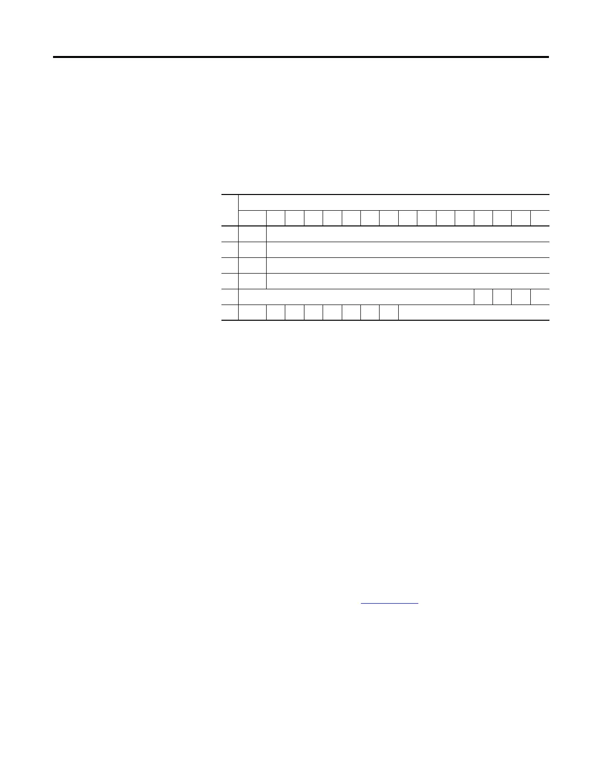
For each input module, slot x, words 0…3 in the input data file contain the analog
values of the inputs.
The bits are defined as follows:
• SGN = Sign bit in two’s complement format.
• Sx = General status bit for channels 0 through 3. This bit is set (1) when an
error (over- or under-range) exists for that channel.
• Ux = Under-range flag bits for channels 0 through 3. These bits can be
used in the control program for error detection.
• Ox = Over-range flag bits for channels 0 through 3. These bits can be used
in the control program for error detection.
Configuration Data File
The manipulation of the bits from this file is normally done with programming
software, such as RSLogix 500, RSLogix 5000, or RSNetWorx for DeviceNet,
during initial configuration of the system. In that case, graphical screens are
provided by the programmer to simplify configuration. However, some systems,
like the 1769-ADN DeviceNet adapter, also allow the bits to be altered as part of
the control program using communication rungs. In that case, it is necessary to
understand the bit arrangement. Refer to the Compact I/O Analog Modules
User Manual, publication number 1769-UM002
for additional details.
Word
Bit Position
15 14131211109876543210
0 SGN Analog Input Data Channel 0
1 SGN Analog Input Data Channel 1
2 SGN Analog Input Data Channel 2
3 SGN Analog Input Data Channel 3
4 Not Used S3 S2 S1 S0
5 U0 O0U101U2O2U3O3Set to 0

 Loading...


