28
2. The Specifications of the Interfaces
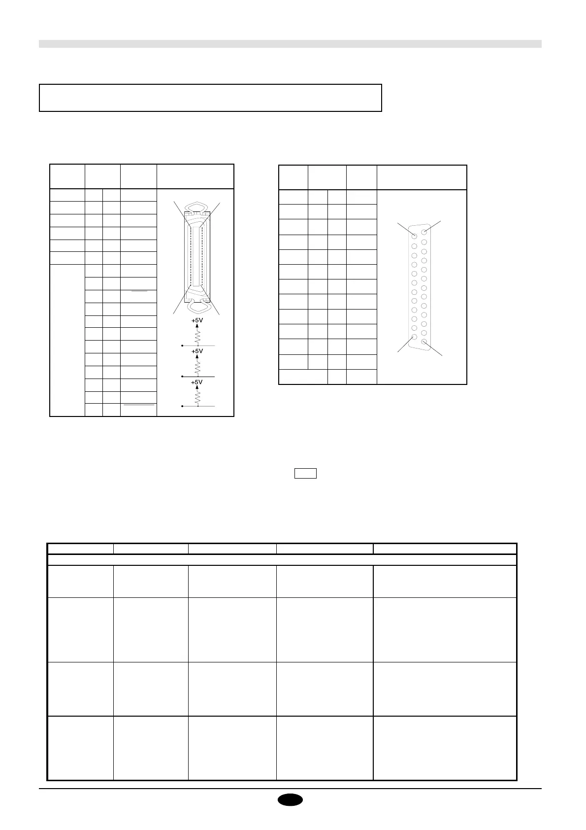
Serial Interface (RS-232C)
Connector
Signal
Name
Terminal
Number
Signal
Name
Pin Connection
NC 36 18 HIGH***
HIGH* 35 17 GND
NC 34 16 GND
GND 33 15 NC
HIGH* 32 14 NC
NC 31 13 HIGH**
GND
30 12 GND
29 11 BUSY
28 10 ACK
27 9 D7
26 8 D6
25 7 D5
24 6 D4
23 5 D3
22 4 D2
21 3 D1
20 2 D0
19 1 STROBE
100 Ω
1.2 KΩ
3.3 KΩ
** =
* =
*** =
36
.
.
.
.
.
.
.
.
.
.
.
.
.
.
.
.
19
25
.
.
.
.
.
.
.
.
.
.
14
13
.
.
.
.
.
.
.
.
.
.
.
1
Signal
Name
Terminal
Number
Signal
Name
Pin Connection
NC 25 13 NC
NC 24 12 NC
NC 23 11 NC
NC 22 10 NC
NC 21 9 NC
DTR 20 8 NC
NC 19 7 SG
NC 18 6 DSR
NC 17 5 CTS
S.RXD 16 4 RTS
NC 15 3 RXD
S.TXD 14 2 TXD
1FG
Device control instructions
Device control instructions are used to determine the communication sequence between the cutting machine and computer
through RS-232C interface and/or tell the cutting machine the current computer state. among them, some device control
instructions set the output specifications of mode 2 instructions.
Each device control instruction is organized with three letters: ESC (1Bh), “.” and one upper case letter. Device control
instructions are of two types: one with parameters and the other without parameters.
Parameters can be omitted. A semicolon “;” is used as a delimiter to separate parameters if they are input in succession. A
“;” without parameters means that parameters were omitted.
If parameters are omitted, the default value is set. For a device control instruction with parameters, a terminator needs to be
input in order to signify the end of instructions. A colon “:” is used as the terminator which cannot be omitted.
18
.
.
.
.
.
.
.
.
.
.
.
.
.
.
.
.
1
Parallel Interface (in compliance with
specifications of Centronics)
Connector
Instruction Format Parameter Range ([ ] is default) Explanation
Handshake Instructions
ESC .B [ESC].B None Outputs the current remaining buffer capacity.
Output Remaining
Buffer Capacity
ESC .M [ESC].M<P1>;<P2>; P1:Delay time 0—32767(msec) [0(msec)] Sets handshake output specifications.
Set Handshake <P3>;<P4>;<P5>;<P6>: P2:Output trigger character [0(Sets nothing)]
Output P3:Echo terminator [0(Sets nothing)]
Specifications (1) P4:Output terminator [13([CR])] Note:When you specify some values to <P4> and
P5:Output terminator [0] <P5>, always set 0 to <P6>. When you specify
P6:Output initiator [0(Sets nothing)] some value to <P6>, always set 0 to <P5>.
ESC .N [ESC].N<P1>;<P2>; P1:Intercharacter delay 0—32767(msec) [0(msec)] Sets an intercharacter delay, and also an Xoff chara-
Set Handshake <P3>;•••••;<P11>: P2—P11 [All 0(Sets nothing)] cter for performing the Xon/Xoff handshake.
Output :Xoff character (for Xon/Xoff)
Specifications (2) Immediate response character
(for ENQ/ACK)
ESC .H [ESC].H<P1>;<P2>; P1:The number of bytes for 0—15358(byte) [80(byte)] When receiving the ENQ character set by <P2>,
Sets ENQ/ACK <P3>;••••••••;<P12>: data block [0(Sets nothing)] compares the value set by <P1> and the remaining
Handshake Mode1 P2:ENQ character [All 0(Sets nothing)] buffer capacity, and returns the ACK character to
P3—P12 the host computer when the remaining buffer
:ACK character (only when capacity is larger. The [ESC].H with no parameter
<P2> is set) performs a dummy handshake.
 Loading...