101
Chapter 4 Using the XV-5050 Effects
Chapter 4
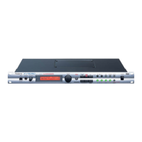
87: ISOLATOR 2
This adds a filter to the ISOLATOR effect. Isolator is an equalizer
that radically cuts the volume of selected frequencies, allowing you
to create special effects to the sound by cutting the volume in various
frequency ranges.
fig.02-087m
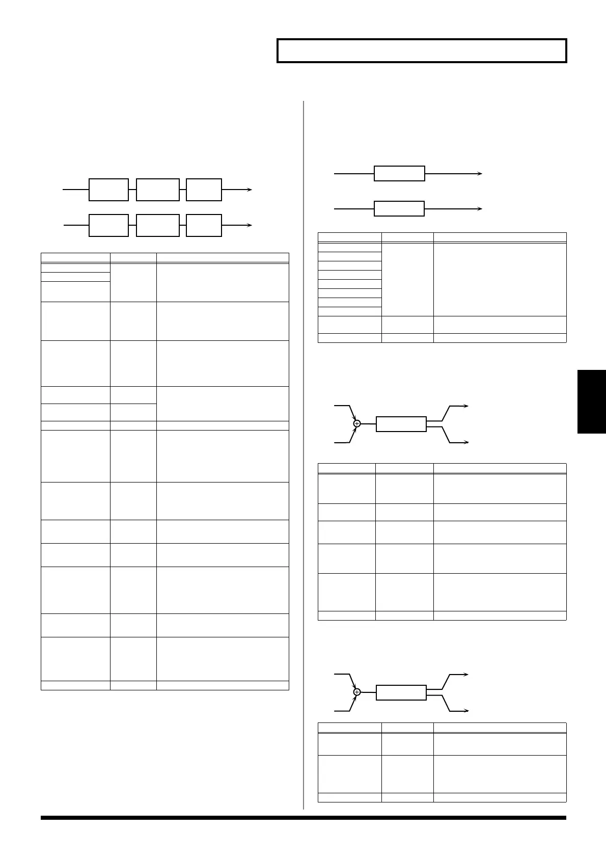
88: St SPECTRUM (Stereo Spectrum)
This is a stereo spectrum. Spectrum is a type of filter that modifies
the timbre by boosting or cutting the levels of specific frequency
ranges.
fig.02-088m
89: 3D AUTO SPIN
Spins the sound across the stereo field.
fig.02-089m
90: 3D MANUAL
Places the 3D effect at a desired location.
Parameter
Value Description
Level Low #
-60-+4 dB These boost and cut each of the High,
Middle, and Low frequency ranges.
At -60 dB, the sound becomes inaudible. 0
dB is equivalent to the input level of the
sound.
Level Middle #
Level High #
AntiPhase Low
Sw
OFF, ON Turns the Anti-Phase function on and
off for the Low frequency ranges.
When turned on, a stereo copy of the
sound is phase-inverted and added to the
signal.
AntiPhase Lo Lev
0-127 Adjusts the level settings for the Low
frequency ranges.
Adjusting this level for certain frequen-
cies allows you to lend emphasis to spe-
cific elements within a sound. (This is
effective only for stereo source.)
AntiPhase Mid
Sw
OFF, ON Settings of the Anti-Phase function for
the Middle frequency ranges
The parameters are the same as for the
Low frequency ranges.
AntiPhase
MidLev
0-127
Filter Switch OFF, ON Turns the filter on/off.
Filter Type LPF, BPF,
HPF,
NOTCH
Type of filter
LPF:
Passes frequencies below the Cutoff.
BPF:
Passes frequencies near the Cutoff.
HPF:
Passes frequencies above the Cut-
off.
NOTCH:
Passes frequencies other than
those near the Cutoff.
Cutoff Freq
0-127 Basic frequency of the filter
The closer to zero this is set, the lower the
cutoff frequency becomes; set it closer to
127, and the cutoff frequency becomes
higher.
Resonance 0-127 Resonance level of the filter
Raising the setting increases the reso-
nance volume near the cutoff frequency.
Filter Slope
-12, -24 dB Filter’s attenuation slope
-24 dB per octave:
steep
-12 dB per octave:
gentle
Filter Gain
0-24 dB Compensates for volume reductions in
selected frequency ranges caused by
some filters.
The level of compensation increases as the
value is increased, thus raising the vol-
ume.
Low Boost Sw
OFF, ON Turns Low Booster on/off.
This emphasizes the bottom frequencies
to create a heavy bass sound.
Low Boost Level
0-127 Increasing this value gives you a
heavier low end.
* Depending on the Isolator and filter
settings, this effect may be hard to
hear.
Level 0-127 Output level
L in
R in
L out
R out
Low
Boost
Isolator Filter
Low
Boost
Isolator Filter
Parameter
Value Description
250Hz Gain -15-+15 dB
Gain of each frequency band
500Hz Gain
1000Hz Gain
1250Hz Gain
2000Hz Gain
3150Hz Gain
4000Hz Gain
8000Hz Gain
Band Width Q 0.5, 1.0, 2.0,
4.0, 8.0
Simultaneously adjusts the width of all the
frequency bands.
Level #
0-127
Output level
Parameter
Value Description
Azimuth
L180-R180
Sets the location at which the sound stops
when rotation ends.
A setting of “0” positions the sound in the
center.
Speed # 0.05-10.00 Hz,
note *2
Speed of rotation
Clockwise
-, +
Direction of rotation
-:
counterclockwise rotation
+:
clockwise rotation
Turn # OFF, ON
Stops or starts the rotation.
ON:
The sound rotates.
OFF:
Rotation stops at the location speci-
fied by Azimuth.
Output Mode SPEAKER,
PHONES
Selects the method by which the effect is
sent to the OUTPUT jacks.
The optimal 3D effect is achieved if you
select SPEAKER when using speakers, or
PHONES when using headphones.
Level
0-127
Output level
Parameter
Value Description
Azimuth #
L180-R180
Specifies the location.
A setting of “0” positions the sound in the
center.
Output Mode
SPEAKER,
PHONES
Selects the method by which the effect is
sent to the OUTPUT jacks.
The optimal 3D effect is achieved if you
select SPEAKER when using speakers, or
PHONES when using headphones.
Level 0-127
Output level
L in
R in
L out
R out
Spectrum
Spectrum
L out
R out
L in
R in
3D Auto
L out
R out
L in
R in
3D Manual
XV-5050_e.book 101 ページ 2003年6月27日 金曜日 午後3時14分
 Loading...