Hardware Installation and Reference Guide Installing the Switch
66
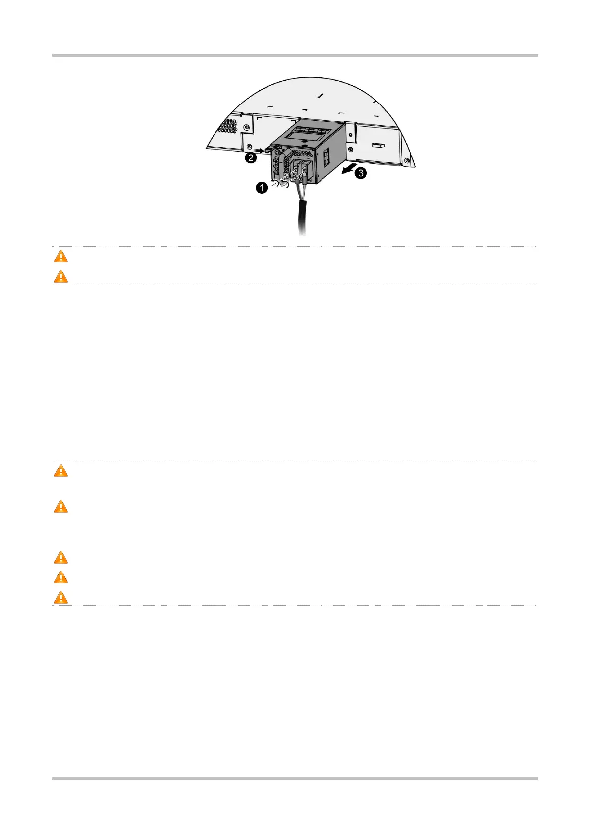
Pull the module out of the slot gently.
Install the filler panel in the empty slot to allow for adequate airflow.
3.5 Grounding the Switch
Connect the PGND to the grounding lug of the rack and then connect the grounding lug to the grounding bar of the equipment room.
Notes
The sectional area of the grounding wire should be determined according to the possible maximum current. Cables of good
conductor should be used.
Do not have bare wires exposed
Grounding resistance: Less than 1 ohm.
To guarantee the security of the person and the device, the switch must be grounded properly. The grounding resistance between
the chassis and the ground should be less than 1ohm.
The maintenance personnel should check whether the AC socket is reliably connected to the protective ground of the building. If
not, the maintenance personnel should use a protective earth conductor from the AC outlet protective earth terminal to the
building protective earth.
The power socket should be installed near the device and easily accessible.
The AC power should be connected to an output socket with a ground connection using a power cord.
When installing the switch, connect the grounding first and disconnect it last.
3.6 Connecting Cables
Notes
Distinguish single-mode and multi-mode fiber-optic cables and ports.
Avoid a small bend radius at the connector.
Bending Steps
1. Connect the RJ45 connector of an Ethernet cable to the Ethernet port on the device, and the other end to a PC.
 Loading...