English _39
● INSTALLATION & CONNECTION
Connecting an external RS-485 device (SNB-6003/SNB-6004)
Connect the camera with an external device using the [RS-485 +, -] ports.
You can control the pan/tilt operations of the camera via RS-485 communications.
`
The GND connection is recommended for RS-485 communications. If you encounter a communication
failure, connect the GND pin as appropriate to correct the GND level between camera and external device.
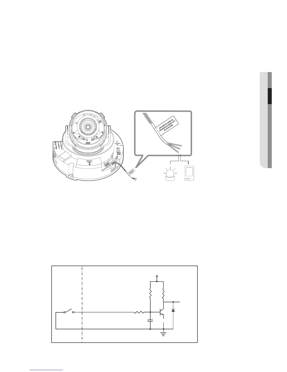
Connecting to the I/O port box (SND-6083/SND-6084)
Connect the Alarm I/O cable to the corresponding port of the inner port box.
• ALARM OUT : Used to connect the alarm output signal.
• ALARM IN : Used to connect the alarm input sensor or external day/night sensor.
• GND : Used for earth-grounding.
To connect the external sensor
Connect one strand of each signal line (2-strand) of the sensors to the [ALARM IN] port,
and connect the other strand to the [GND] port.
Alarm In Wiring Diagram
Sensor
GND
RESISTORALARM IN (5mA SINK)
RESISTOR RESISTOR
VCC_3.3V
DIODE
GND
MLCC
TRANSISTOR
External
connection
Inside of the camera
Alarm Sensor
 Loading...