- 92 -
Electrical Adjustments
S 0 – Temperature Monitor Indication
– 0 LM76 (Temp) Monitor (°C) Temp. Sensor (Intake) – – –
– 1 LM76 (Temp) Monitor (°C) Temp. Sensor (Inner) – – –
– 2 Thermistor Monitor (°C) Temp. Thermistor (Inner) – – –
– 3 Thermistor Monitor DAC value – – –
S 1 – Pressure Monitor Indication
– 0 MPXA4114A(Pressure) Monitor Pressure Sensor – – –
– 0 MPXA4114A(Pressure) Monitor Pressure Sensor (mmHg) – – –
– 0 MPXA4114A(Pressure) Monitor Pressure Sensor (hpa) – – –
S 10 – RS232C Set
– 0 Baud rate RS232C Baud rate (0 : 19200 / 1 : 9600) 0 / 1 0 –
S 11 – PJ-Net Set
– 0 Reset Disable PJ-Net Reset (0 : Enable / 1 : Disable) 0 / 1 0 –
S 20 – Logo On/Off
– 0 Logo On/Off (0 : Menu Operation / 1 : Prohibition) 0 / 1 0 –
S 30 – Color Shading / Gamma Correction
– 0 Color shading Correction On/Off (0 : Off / 1 : On) 0 / 1 1 –
– 1 Gamma Correction On/Off (0 : Off / 1 : On) 0 / 1 1 –
S 40 – Dimmer Control
– 0 Dimmer On/Off (0 : Menu Operation / 1 : Off) 0 / 1 1 –
– 1 Dimmer Level LAMP1 (0 : 264W ~ 15 : 330W) 0 ~ 15 15 –
– 2 Dimmer Level LAMP2 (0 : 264W ~ 15 : 330W) 0 ~ 15 15 –
– 3 Dimmer Level LAMP3 (0 : 264W ~ 15 : 330W) 0 ~ 15 15 –
– 4 Dimmer Level LAMP4 (0 : 264W ~ 15 : 330W) 0 ~ 15 15 –
S 50 – Auto Picture Control
– 0 Auto Picture On/Off (0 : Menu Operation / 1 : Off ) 0 / 1 1 –
S 80 – Projector Time
– 0 Projector Time Reset Do not touched. (Available at No.10) 0 ~ 10 0 –
S 91 – Projector Warning History
– 0 Warning_Log_1 History in front of 1 step 0 ~ 32767 0 –
– ~ : : : –
– 49 Warning_Log_50 History in front of 1 step 0 ~ 32767 0 –
– 50 Warning_Log_Reset Do not touched. (Available at No.10) 0 ~ 10 0 –
S 113 – Reset Frequency Counter
– 0 Lamp 1 Lamp 1 Total Lighting Time 0 ~ 127 0 –
– 1 Lamp 2 Lamp 2 Total Lighting Time 0 ~ 127 0 –
– 2 Lamp 3 Lamp 3 Total Lighting Time 0 ~ 127 0 –
– 3 Lamp 4 Lamp 4 Total Lighting Time 0 ~ 127 0 –
S 115 – Lamp Go Out
– 0 Lamp Go Out 0 : Disable / 1 : Enable 0 / 1 0 –
S 116 – Lamp Replace Display
– 0 Lamp Replace Display 0 : Disable / 1 : Enable 0 / 1 0 –
S 140 – Fan Output Level
– 0 Fan A Min (
✽) Fan A Driving Voltage Adj. at TP7611 0 ~ 255 220 –
– 1 Fan A Max (
✽) Fan A Driving Voltage Adj. at TP7611 0 ~ 255 20 –
– 2 Fan B Min (
✽) Fan B Driving Voltage Adj. at TP2661 0 ~ 255 200 –
– 3 Fan B Max (
✽) Fan B Driving Voltage Adj. at TP2661 0 ~ 255 20 –
– 4 Fan C Min (
✽) Fan C Driving Voltage Adj. at TP2671 0 ~ 255 175 –
– 5 Fan C Max (
✽) Fan C Driving Voltage Adj. at TP2671 0 ~ 255 25 –
– 6 Fan D1 Min (
✽) Fan D1 Driving Voltage Adj. at TPFN1 0 ~ 255 200 –
– 7 Fan D1 Max (
✽) Fan D1 Driving Voltage Adj. at TPFN1 0 ~ 255 50 –
– 8 Fan D2 Min (
✽) Fan D2 Driving Voltage Adj. at TPFN2 0 ~ 255 200 –
– 9 Fan D2 Max (
✽) Fan D2 Driving Voltage Adj. at TPFN2 0 ~ 255 50 –
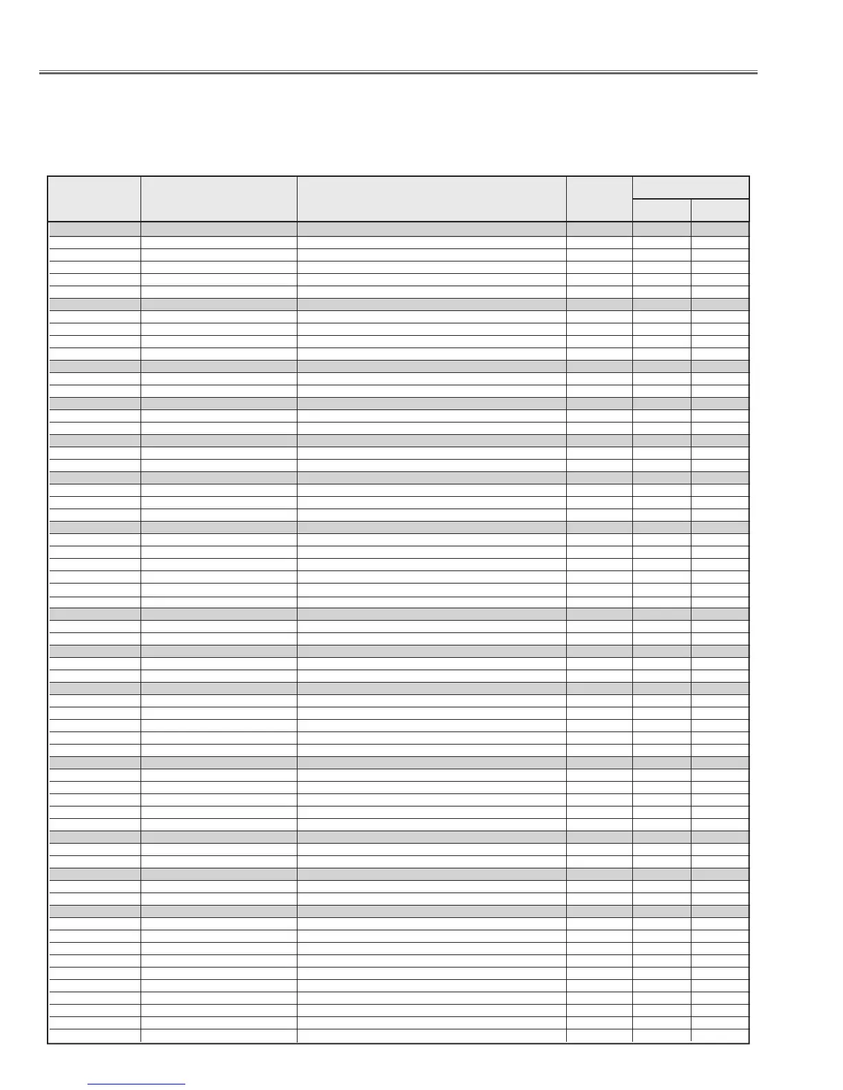
Group
No.
Data
Range
Initial Value
Function
Item
No.
Item
PLC-XF47
CAUTION : These initial values are the reference data written from the CPU ROM to the memory IC when the new memory
IC replaced. The adjustment items indicated with "
j
" are required to readjust following to the "Electrical
adjustments". Other items shoul be used with the initial value.
n
Service Adjustment Data Table
 Loading...


