-62-
Troubleshooting
No Power
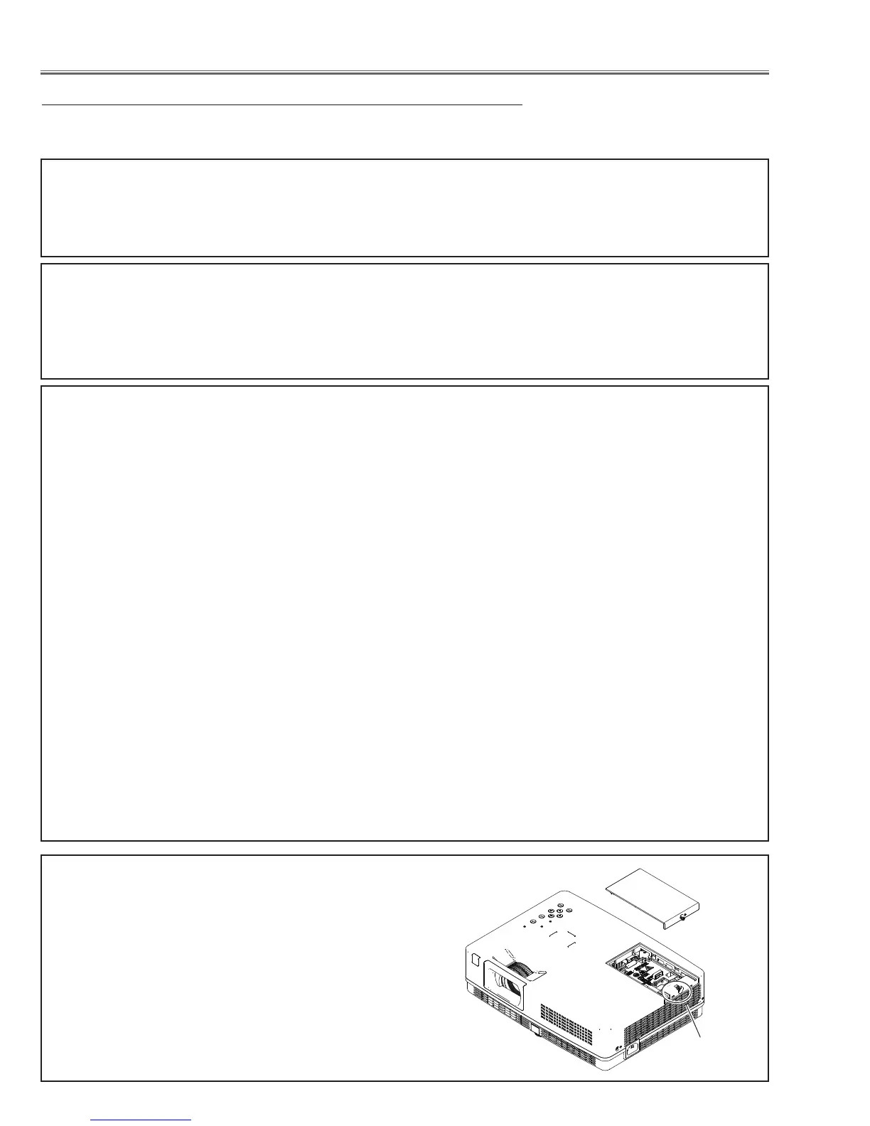
Lamp Cover switch
Make sure that the lamp cover is mounted correctly. If not
or the lamp cover removed, the lamp does not light on for
the safety. Check the lamp cover and lamp cover switch
(SW902).
- When all of LED indicators are not lighting, the symptom indicates that the primary power supply circuit does
not operate properly. Check the power primary circuit and parts as follow;
AC cord, F601 (Fuse), Power board,
SW601 (Thermal sw.) short in normal
SW601 opens when the surrounding temperature of the switch exceeds 85°C.
This projector provides a function which can be specified a defective area simply by indicating the LEDs. Connect the
AC cord and press the Power button once and then check the LED indication.
- When the WARNING (red) and POWER (red) indicators are blinking, the symptom indicates that the projector
detected an abnormal temperature risen inside the projector. Check the air filters and remove the object near the
intake and exhaust fan openings, and wait until the POWER indicator stops blinking, and then try to turn on the
projector.
The internal temperature is monitored by sensor ICs, IC8831, IC8821 on the Main board and IC8811 on
the R/C board.
- When the WARNING indicator lights red, the symptom indicates that the projector detected an abnormality in
the cooling fan operation or in the power supply secondary circuits. Check fan operation and power supply lines,
and the driving signal status.
The P_FAIL signal (Error: L) is sent to pin 215 of IC301<SYSTEM CONTROL> when the abnormality occurred
inside the projector, and then the IC301 sends the shutdown signal, LAMP_DC_ON, to the power supply circuit
to stop its operation, and signal LAMP_SCI to the lamp ballast board via IC4891 and SW902<lamp cover switch>
to stop operation of the lamp circuit.
An abnormality occurs on the secondary power supply;
Check power supplies S16V, S6V, S-5V. P_FAIL signal becomes “Low” when the abnormality occurs on any
of the power supply lines.
An abnormality occurs on the fan control circuit;
Check FN001, FN002, FN003, FN004, FN005 and peripheral circuit.
If any of the fans has an error, the fan lock signal drives Q3601 becomes "High". As the result, signal
FAN_ERR becomes Low and is sent to lamp ballast board to stop lamp circuit.
An abnormality occurs on the drive signals;
ON_150V signal (Power-on: H) is output from pin 95 of IC301 and switches IC592,15.5VL supply circuit,
ON_33V signal (Power-on: H) is output from pin 188 of IC301 and switches IC5621, 1.0V and Q3582 33V
supply circuit.
LAMP_DC_ON signal (Power-on: H) is output from pin 89 of IC301 and supplied to the P.C Control IC,
IC621, on the power supply board through Q691, and PC663.
LAMP_SCI signal (Power-on: H) is output from pin 14 of IC9885 and applied to pin 2 of IC4891 and out
put pin 4 and then supplied to the lamp ballast board through SW902<Lamp Cover SW>.
LAMP_DET signal at the pin 285 of IC301 is applied from the lamp ballast unit. If the abnormality occurred
on the lamp ballast unit, LAMP_DET signal becomes “High” and then IC301 shuts down the power supply
circuit.
SW902
 Loading...