-61-
Electrical Adjustment
1. Receive the 50%-Whole Gray computer signal with
Input1 [RGB] mode.
2. Enter the service mode.
3. Select group no. “100”, item no. “92” and change
data value to “2” to reduce the panel frequency.
4. Project only red light component to the screen.
5. Select group no. “101”, item no. “0” and change
data value to obtain the minimum flicker on the
screen.
6. Project only green light component to the screen.
7. Select item no. “1” and change data value to obtain
the minimum flicker on the screen.
8. Project only blue light component to the screen.
9. Select item no. “2 and change data value to obtain
the minimum flicker on the screen.
10. Select group no. “100”, item no. “92” and change
data value to “0” to reset the panel frequency.
n Common Center adjustment
1. Receive the 16-step gray scale computer signal with
Computer1 [RGB] mode.
2. Enter the service mode, select group no. “100” item
no. “7” (Red) or “8” (Blue), and change Data values
respectively to make a proper white balance.
Confirm that the same white balance is obtained in video
and computer input.
. White Balance adjustment [PC]
1. Receive the 16-step grey scale composite video sig-
nal with Video mode.
2. Enter the service mode, select group no. “100” item
no. “7” (Red) or “8” (Blue), and change Data values
respectively to make a proper white balance.
Confirm that the same white balance is obtained in video
and computer input.
⁄0 White Balance adjustment [Video]
⁄1
White Uniformity Adjustment
If you find the color shading on the screen, please ad-
just the white uniformity by using the proper computer
and “Color Shading Correction” software supplied sepa-
rately.
The software can be ordered as follows;
COLOR SHADING CORRECTION Ver. 4.00
Service Parts No. 645 075 9611
1. Receive the 16-step grey scale computer signal with
Computer1 [RGB] mode.
2. Enter the service mode.
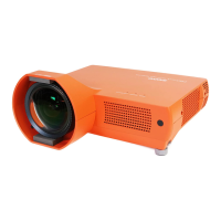
3. Connect an oscilloscope to test point “TP35G” (+)
and chassis ground (-).
4. Select group no. “100”, item no. “6” and change data
value to adjust amplitude “a” to be 1.1 ±0.1V.
(a)
white level
white level
m 50% luminance adjustment [PC]
1. Receive the 100%whole-white composite video signal
with Input3 [Video] mode.
2. Enter the service mode.
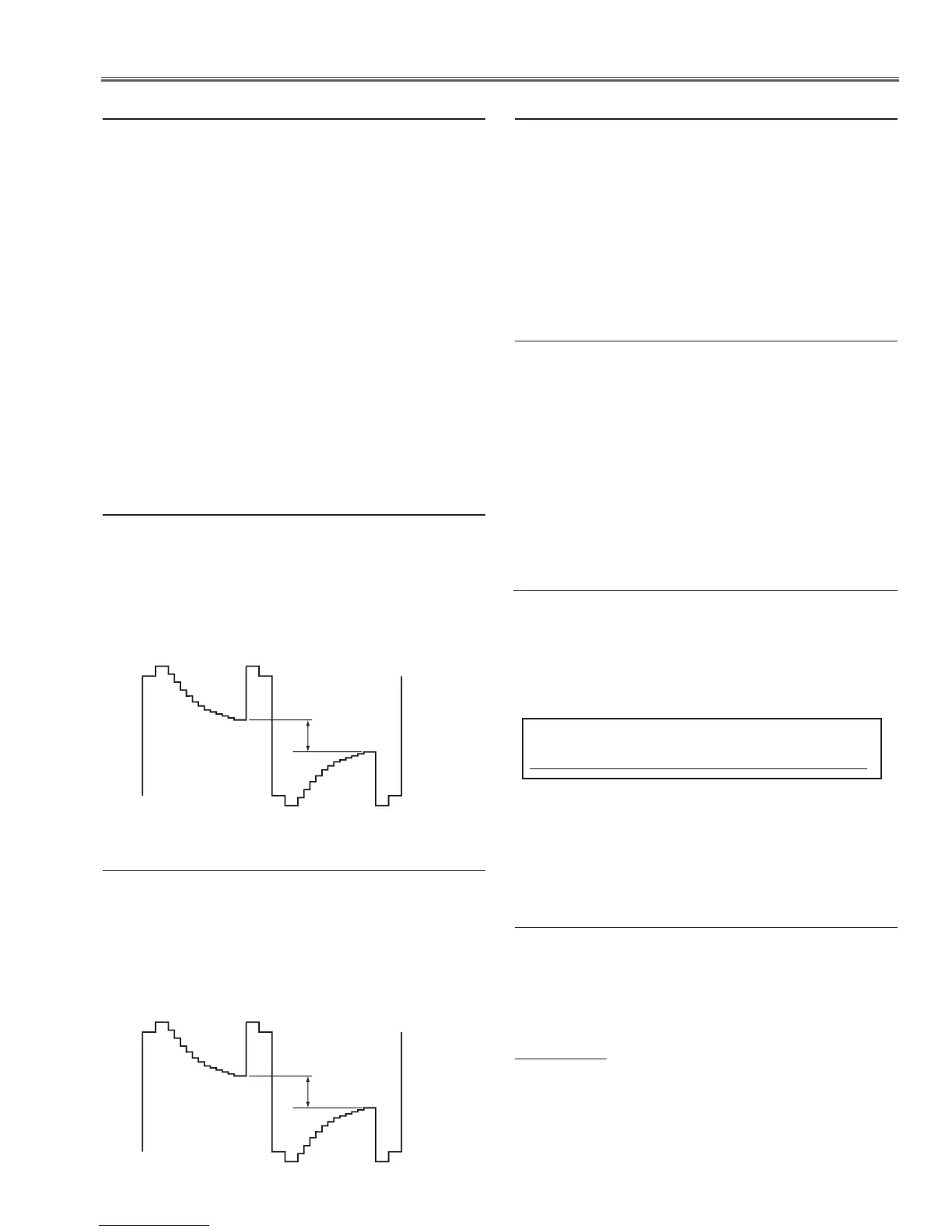
3. Connect an oscilloscope to test point “TP35G” (+)
and chassis ground (-).
4. Select group no. “100”, item no. “6” and change data
value to adjust amplitude “a” to be 2.2 ±0.1V.
(a)
white level
white level
, 50% luminance adjustment [Video]
1. Enter the service mode, select group no. “251” and
item no. “0” .
2. To start the adjustment, change data value from “0”
to “1”. After the auto-calbration completed, "OK" will
appear on the screen.
IMPORTANT
Before taking this adjustment, you need to replace the
air filter with new one or clean up it and make sure the
filter is securely installed.
⁄2 Filter Calibration adjustment
 Loading...