-95-
Chassis Description
Diagnosis of Power Failure with RS-232C port
This projector provides a function to get the error information of the projector by using the RS-232C serial port for the
power failure diagnosis.
The further error information of the power failure and fan failure can be found out by using this function.
Diagnosis procedure
1 Connect a RS-232C serial cross cable to SERIAL PORT IN on the projector and serial port on the PC.
2 Launch a communication software "Hyper terminal" provided with PC and setup the communication condition as
follows;
Baud rate : 19200 bps
Parity check : none
Stop bit : 1
Flow control : none
Data bit : 8
3 Turn on the projector. Check that the LED shows a pow-
er failure. (All the LEDs except LAMP LED are blinking)
4 Type a diagnosis command of the power failure “CR
ALLPFAIL” and press a "ENTER" key within 1 second
on the command window of the software.
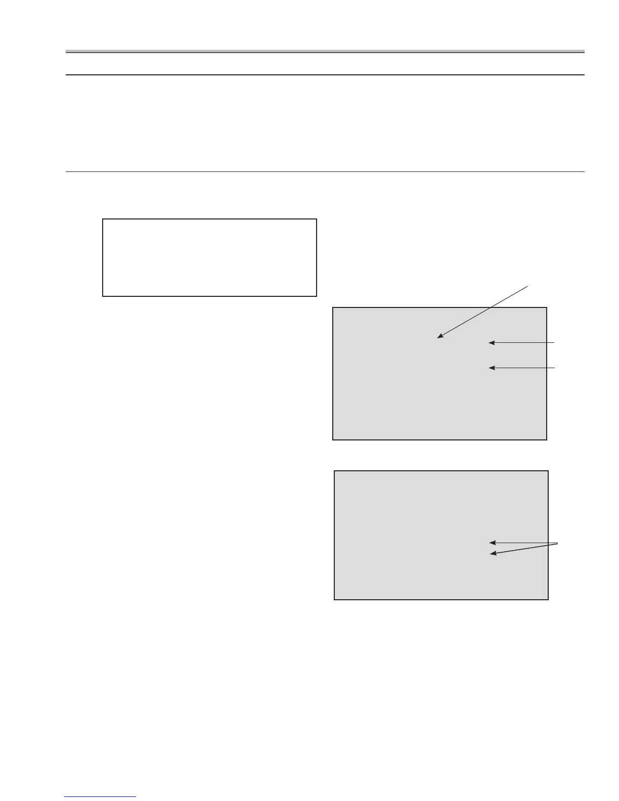
The error information will be listed on the window as
the right.
Check the status column. If “NG” is listed, the power
failure occurs on its signal line(Power Line Name). In
case of the right table, this error information means that
the power failure occurs on the S1.2V power supply on
the FPGA circuit on the main board. Check if the parts
connected to 6V power supply line are defective.
Also the error information may be listed multiple as the
below;
In the above case, 2 kinds of causes are considered.
One is the power failure occurs on the multiple places
at the same time, other is a power failure affects mul-
tiple power supply lines even if the failure occurs on the
single place.
In the first case, Check if the parts connected to the mul-
tiple power supply lines are defective. In the later case,
determine a failure point referring to the power supply
flow chart on previous page. Basically, if the power fail-
ure occurs on the upper side of power supply, the power
failure is also detected on lower side of power supply frequently. If the failure occurs on the lower side of power
supply, it is lightly affected to the upper side of the power supply. In the above case, because the failure occurs on
the S6V power supply on the MAIN circuit on the main board, the failure is also detected on the 5V power supply
and S5V power supply on the main board.
* See "Power Failure Detection Tree" for further description of the Error Information.
CR ALLPFAIL
000 MAIN, 1.8/1.0V OK
000 MAIN, S-5V OK
000 FPGA, S1.2V NG
000 MAIN, 15/9/5V OK
000 MAIN, S5/S9V OK
000 PJ_N/AV,3.3/S5V OK
000 FAN, FANLOCK OK
........ ............... ......... ......
Status
Error Information
(Signal Name)
Error
CR ALLPFAIL
000 MAIN, 1.8/1.0V OK
000 MAIN, S-5V OK
000 FPGA, S1.2V OK
000 MAIN, 15/9/5V NG
000 MAIN, S5/S9V NG
000 PJ_N/AV,3.3/S5V OK
000 FAN, FANLOCK OK
........ ............... ......... ......
Error
 Loading...