861-9601.9 • INSTALLATION AND OPERATING INSTRUCTIONS • 8DA10 • Revision 11 11/214
Description
Description
6 Panel overview
6.1 Subframe
• Support for switchpanel poles and panel front
• Forms the cable compartment
•Subframe versions
- Standard: Switchgear height 2350 mm
- Higher version: Switchgear height 2570 mm
6.2 Switchpanel pole
•Poles arranged one behind the other.
• One switchpanel pole consists of a vertically arranged housing
(e.g. with integrated vacuum interrupter).
• The busbar housing with integrated three-position disconnector is mounted horizontally
over the switchpanel pole.
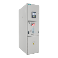
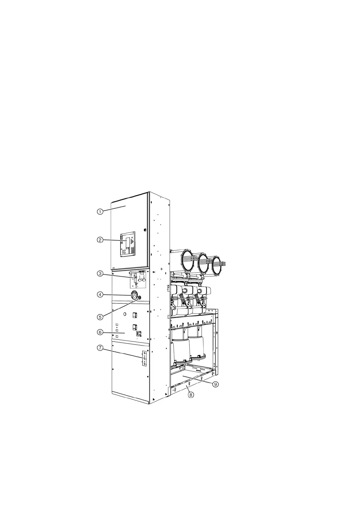
Fig. 3: 8DA10 circuit-breaker panel
①
Low-voltage compartment (standard heights: 850/1200 mm)
②
SIPROTEC bay controller (option)
③
Indication and control board for three-position disconnector with circuit-breaker position indicator
④
Manometer for gas monitoring of the switchpanel pole housing
⑤
Gas filling valve
⑥
Control board for circuit-breaker
⑦
Voltage detecting system
⑧
Frame
⑨
Cable compartment

 Loading...