861-9601.9 • INSTALLATION AND OPERATING INSTRUCTIONS • 8DA10 • Revision 11 27/214
Description
13 Protection and control equipment
The protection equipment and control equipment is designed customer-specifically. T
he devices are installed in the low-voltage compartment or in the low-voltage niche.
Details are given in the respective circuit documentation.
14 Voltage detecting systems
For voltage detection according to IEC 61243-5 and VDE 0682 Part 415 with the following
voltage detecting systems:
• LRM plug-in sockets
• VOIS+, VOIS R+ (option)
• CAPDIS -S1/-S2+ (option)
• WEGA 1.2/2.2 (option)
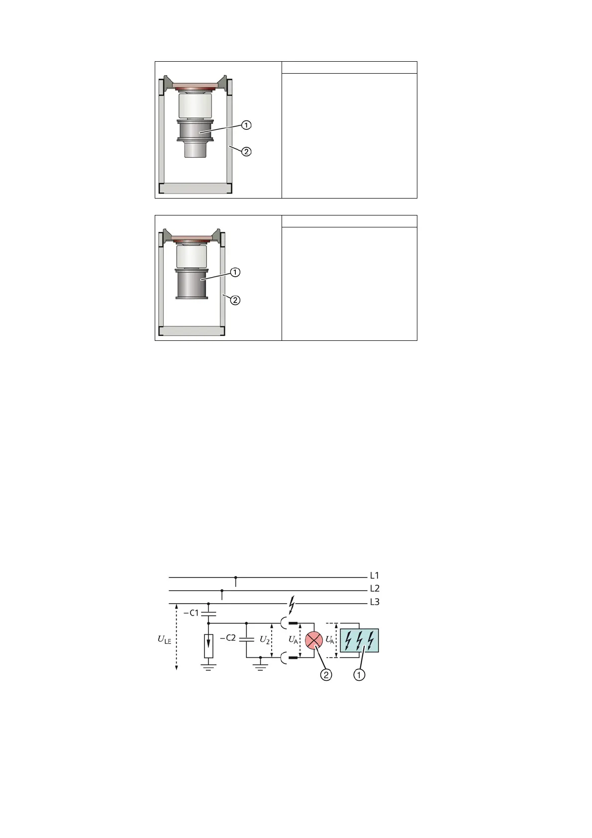
• -C1: Capacitance integrated into bushing
• -C2: Capacitance of the connection leads and the voltage indicator to earth
•U
LE
= U
N
/√3 during rated operation in the three-phase system
•U
2
= U
A
= Voltage at the interface (plug-in sockets) of the plug-in voltage indicator or
the test socket of the integrated voltage indicator
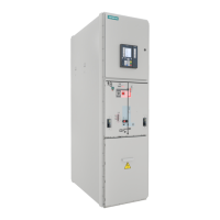
Version 6 Solid-insulated bar connection
1
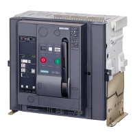
Version 7 Gas-insulated bar connection
1
Fig. 12: Voltage detecting system via capacitive voltage
divider (principle)
①
Integrated voltage indicator
②
Plug-in LRM voltage indicator

 Loading...