861-9601.9 • INSTALLATION AND OPERATING INSTRUCTIONS • 8DA10 • Revision 11 23/214
Description
10.2 Current transformers
Features • According to IEC 61869-2 or EN 61869-2 (depending on the switchgear version)
• Designed as ring-core current transformers:
- Ring core as carrier of secondary winding
- Main circuit corresponds to primary winding
• Arranged outside the primary enclosure (switchgear housing) due to single-pole design of
the panel
• Free of dielectrically stressed cast-resin parts
Mounting locations •On the busbar
• At the panel connection
•On the cable
Electrical data
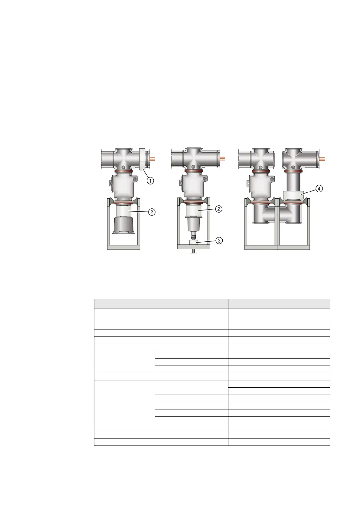
Fig. 9: Current transformer installation (basic scheme)
①
Busbar current transformer (type 4MC4_40)
③
Feeder current transformer (type 4MC4_10)
②
Feeder current transformer (type 4MC4_90)
④
Current transformer on bus sectionalizer
(type 4MC4_40)
Designation Type 4MC4
Operating voltage max. 800 V
Rated short-duration power- frequency withstand voltage
(winding test)
3 kV
Rated frequency 50/60 Hz
Rated continuous thermal current max. 1.2 x rated current (primary)
Rated thermal short-time current, max. 3 s max. 40 kA
Rated current dynamic unlimited
primary 40 A to 2500 A
secondary 1 A And 5 A
Multiratio (secondary) 200 A - 100 A to 2500 A - 1250 A
Core data according to rated primary current max. 3 cores
Measuring core Rating 2.5 VA to 30 VA
Class 0.2 to 1
Overcurrent factor FS 5, FS 10
Protection core Rating 2.5 VA to 30 VA
Class 5 P or 10 P
Overcurrent factor 10 to 30
Permissible ambient air temperature max. 60 °C
Insulation class E

 Loading...