861-9601.9 • INSTALLATION AND OPERATING INSTRUCTIONS • 8DA10 • Revision 11 21/214
Description
10 Current and voltage transformers
10.1 4MT and 4MU voltage transformers
Features • According to IEC 61869-3
• Cast-resin insulated
•Inductive type
• Safe-to-touch due to metal enclosure
Mounting locations •On the busbar
• At the panel connection housing
Electrical data
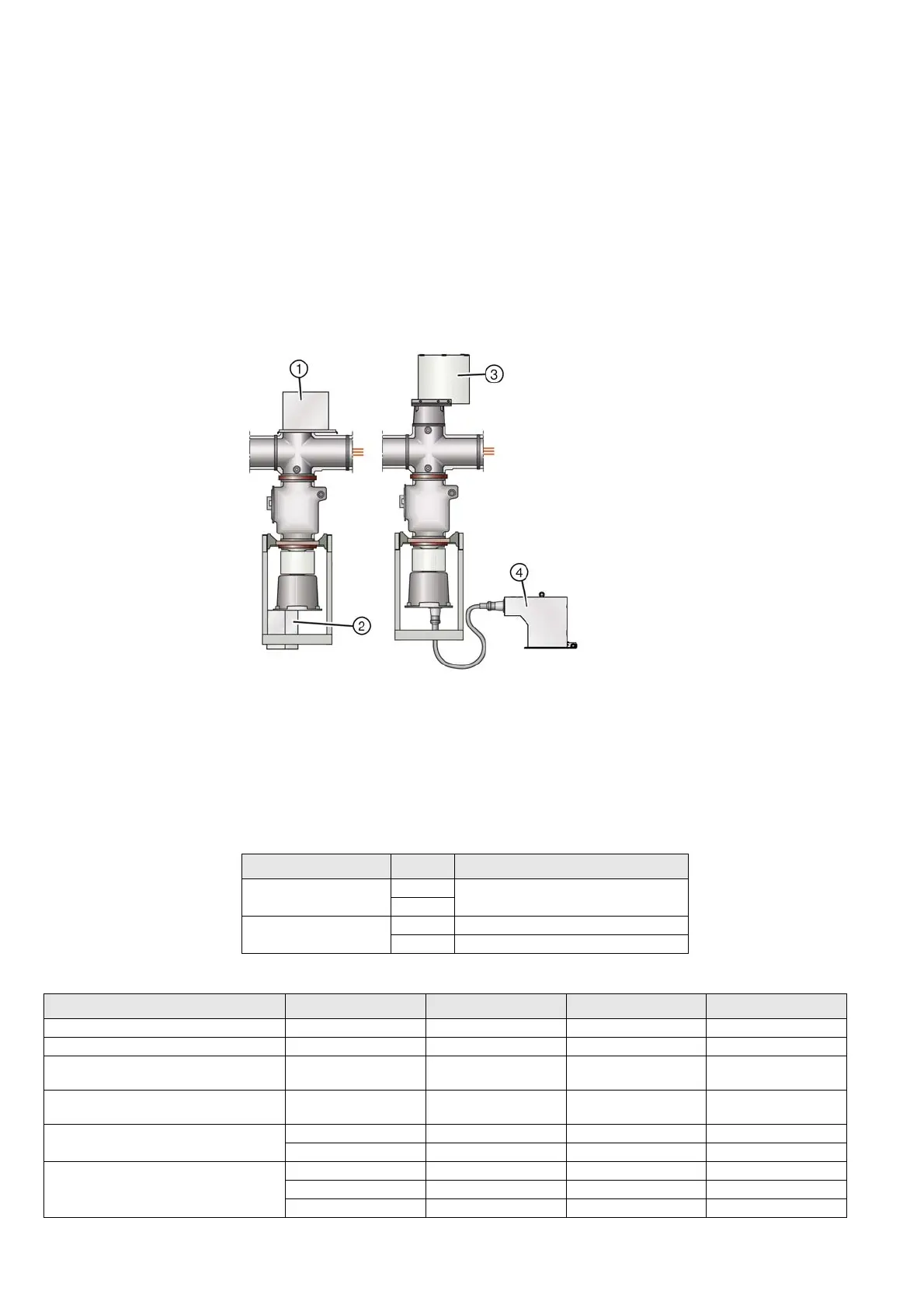
Fig. 7: Voltage transformer installation (basic scheme)
①
Busbar voltage transformer 4MT3
③
Voltage transformer 4MU4 with
three-position disconnector
②
Feeder voltage transformer 4MT7
(connection at panel connection housing)
④
Feeder voltage transformer 4MU3
(not in the panel, connection via flexible
cable with plug size S2 at the panel
connection housing, and metal-enclosed
voltage transformer)
Mounting locations Type Remark
Busbar 4MT3 optionally with three-position
disconnector
4MU4
Panel connection housing 4MU3 external
4MT7 directly plugged in
Designation 4MT3 4MU4 4MT7 4MU3
Operating voltage kV 3.3 to 23.0 24.0 to 38.0 3.3 to 38.0 3.3 to 38.0
Rated voltage kV 24.0 40.5 40.5 40.5
Rated short-duration power-frequency
withstand voltage kV
65.0 95.0 95.0 95.0
Rated lightning impulse withstand voltage
kV
125.0 200.0 200.0 200.0
Rated voltage factor Un / 8h = 1.9 Un / 8h = 1.9 Un / 8h = 1.9 Un / 8h = 1.9
Un / continuous = 1.2 Un / continuous = 1.2 Un / continuous = 1.2 Un / continuous = 1.2
Standard IEC IEC IEC IEC
GOST GOST GOST GOST
GB GB GB GB

 Loading...