Architecture
10 SICAM TM, Installation
Edition 10.2014, DC6-015-2.04
1.1. Mechanical Design
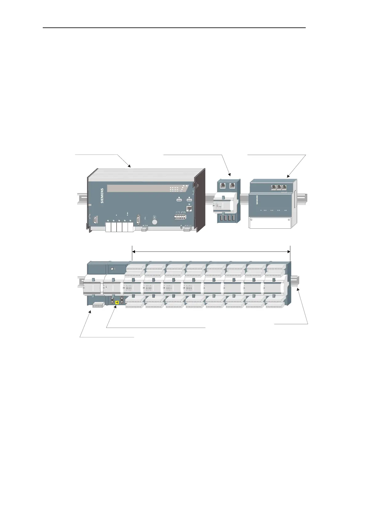
A SICAM TM system consists of one master control element, up to a maximum of 4 bus
interface modules (electrical and/or optical) and up to 16 peripheral elements.
A peripheral element consists of a power supply module, a peripheral control module and up
to a maximum of 8 I/O-modules. The modules are fitted on a TS35 rail (DIN rail).
Optionally the master control element can be configured with up to 2 serial interface modules
(SIM) for the communication with other automation units or control systems.
SICAM
TM 1703 ACP CP-6014
FB
M-PRE/2
M-PRE/3
M-PRE/0
M-PRE/1
NC
TB
PWR
24-60VDC
R
P
X2
1 2 3 4 5 6
Max. 8 I/O-modules
Peripheral control module (elektrical or optical)
Power supply module
TS35 rail
Bus interface module (electrical)
Bus interface module (optical)

 Loading...