12 Monitored lines
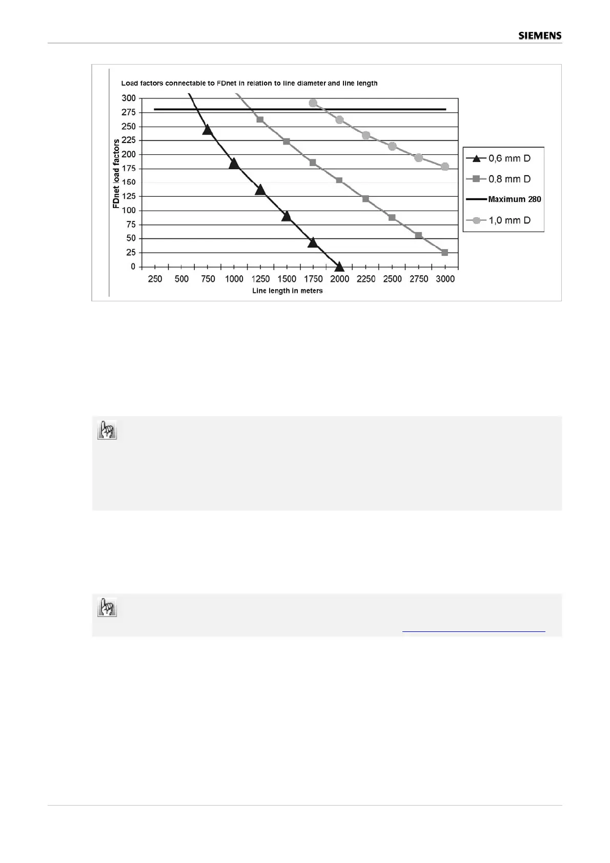
Figure 19: Load factors in relation to line diameter and line length
Example: For a 2000m cable with 0.8 mm ∅, a maximum of 150 load factors may be con-
nected.
The curves allow for the leakage currents occurring with a creeping short circuit and a load
factor increase of 5 detectors with load factor 1 in alarm state.
The line capacity can limit the line length if lines are very long.
Note:
If SIGMALOOP/spur or MS8 wires are run in the same cable as FDnet wires, faults
may occur (above all in the initialization phase) in the SIGMALOOP or when trigger-
ing the alarms of MS8 detectors.
FDnet alarm lines from different modules can be run in the same cable.
Each of the following lines has separate earth fault monitoring:
Loop 1 and 2 respectively spurs 1,2,5,6
Loop 3 and 4 respectively spurs 3,4,7,8
To calculate the power requirement for the Sinteso detector periphery you can also
use the Excel tables on the PSP (Product Support Platform). https://psp.sbt.siemens.com/
92 / 128 BMT Project Planning Guidelines
Best.Nr. A24205-A337-B970 – Edition 12 (03/07)
 Loading...