12 Monitored lines
12.4 Line lengths in the loop/spur
Shielded installation cables, e. g. IY(ST)Y are to be used as lines for the loop.
The maximum wire diameter that can be clamped in the standard detector base is 0.8 mm.
The maximum line length depends on:
• the number of detectors and the cable type
• the maximum line resistance including the resistance of the connected elements (R
max. = 200 Ω)
• the maximum line capacity including all connected capacities (C max. = 200 nF).
Ohm/km, or . element nF/km, or element
IY (St) Y 2x2x0,8 73,2 Ohm 100 nF
IY (St) Y 2x2x0,6 130 Ohm 100 nF
NYM 1,5 mm² 25 Ohm 250 nF
Loop element 0,8 Ohm -
Table 29: Line parameter
Element capacity is very low with regard to the line capacity and therefore not relevant.
The combo detector SDF3500 counts as two address elements in the per-detector line length
calculation.
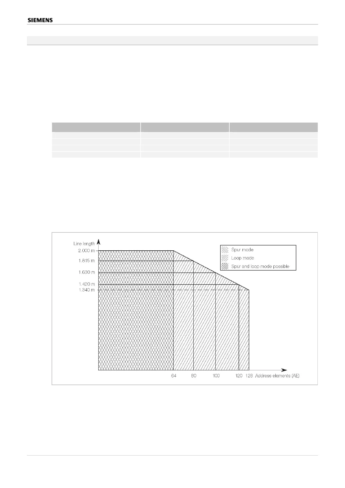
Figure 17 shows the relationships for a 0.8 diameter line. The spur line is a real subset of the
loop line, i.e. up to 64 address elements can be operated on a 2 km line both in the loop and
on the spur. A large number of address elements can only be operated in the loop, the maxi-
mum possible line length drops to approx. 11 m⁄element.
Figure 15: Address element number and line lengths for a 0.8 diameter line
Behaviour is similar in the case of a 0.6 diameter line. The maximum line length here is 1.540
m in the case of zero elements. The maximum possible line length per element drops by ap-
prox. 6
m
⁄element and measures 1.150 m in length with 64 address elements (spur/loop) and 750
in the case of a fully configured loop (128 address elements).
Multifunctional Danger Control and Indicating Panels SIGMASYS C and M (M-Modules) 83 / 128
Best.Nr. A24205-A337-B970 – Edition 12 (03/07)
 Loading...