12-11
TP27, TP37 Equipment Manual
Release 01/00
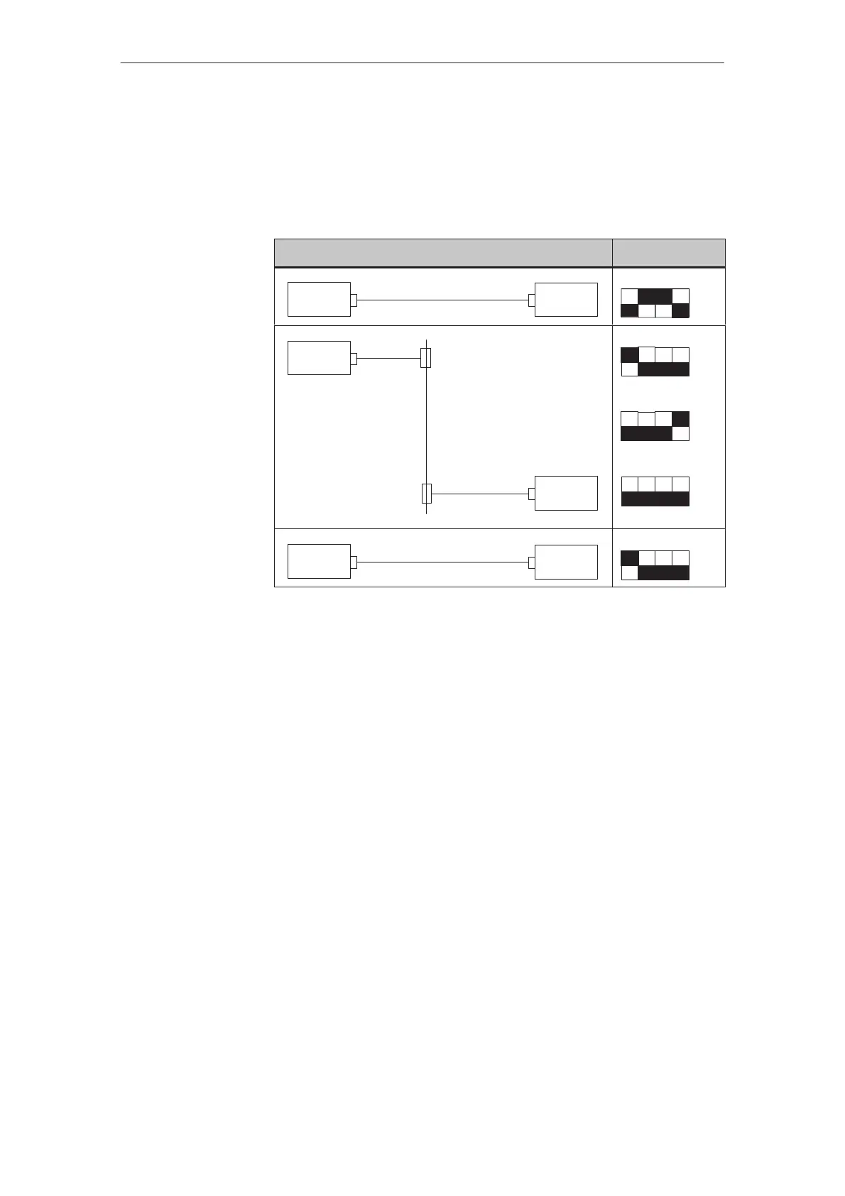
The IF1B interface can be configured by using the DIL switches, located
beside the 9–pin Sub-D connector. This interchanges the RS422 receive data
and the RTS signal. By default, the RTS signal is not required by the
communication peer.
The table shows the permissible DIL switch settings.
i
i
i
i
ommun
ca
on
w
c
e
ng
TP
PLC
RS422/RS485
ON
OFF
1234
PLC
PPI/MPI/PROFIBUS
TP
RTS on pin 4 (default)
ON
OFF
1234
RTS on pin 9 (same as PU)
ON
OFF
1234
No RTS on plug
ON
OFF
1234
PLC
PPI/MPI
Standard cable
TP
ON
OFF
1234
Configure interface
IF1B
Installation

 Loading...