17-5
TP27, TP37 Equipment Manual
Release 01/00
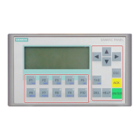
The pin arrays of the module boards DKM A and DKM B have the following
pin assgnment:
12345678910
GND
1
DO 8
DO 6
DO 4
DO 2
+24V DC ext.
DO 1
DO 3
DO 5
DO 7
DKM A
DO 16
DO 14
DO 12
DO 10
+24V DC ext.
DO 9
DO 11
DO 13
DO 15
DKM B
GND
1
1)
floating
The components to be triggered (e.g. relays, signaling indicators, etc.) are
connected by means of the five–pin connectors supplied:
S Connect the wires (conductor cross–sections 0.5 ... 2.5 mm2
)
S Plug the terminal blocks onto the pins of the DKM
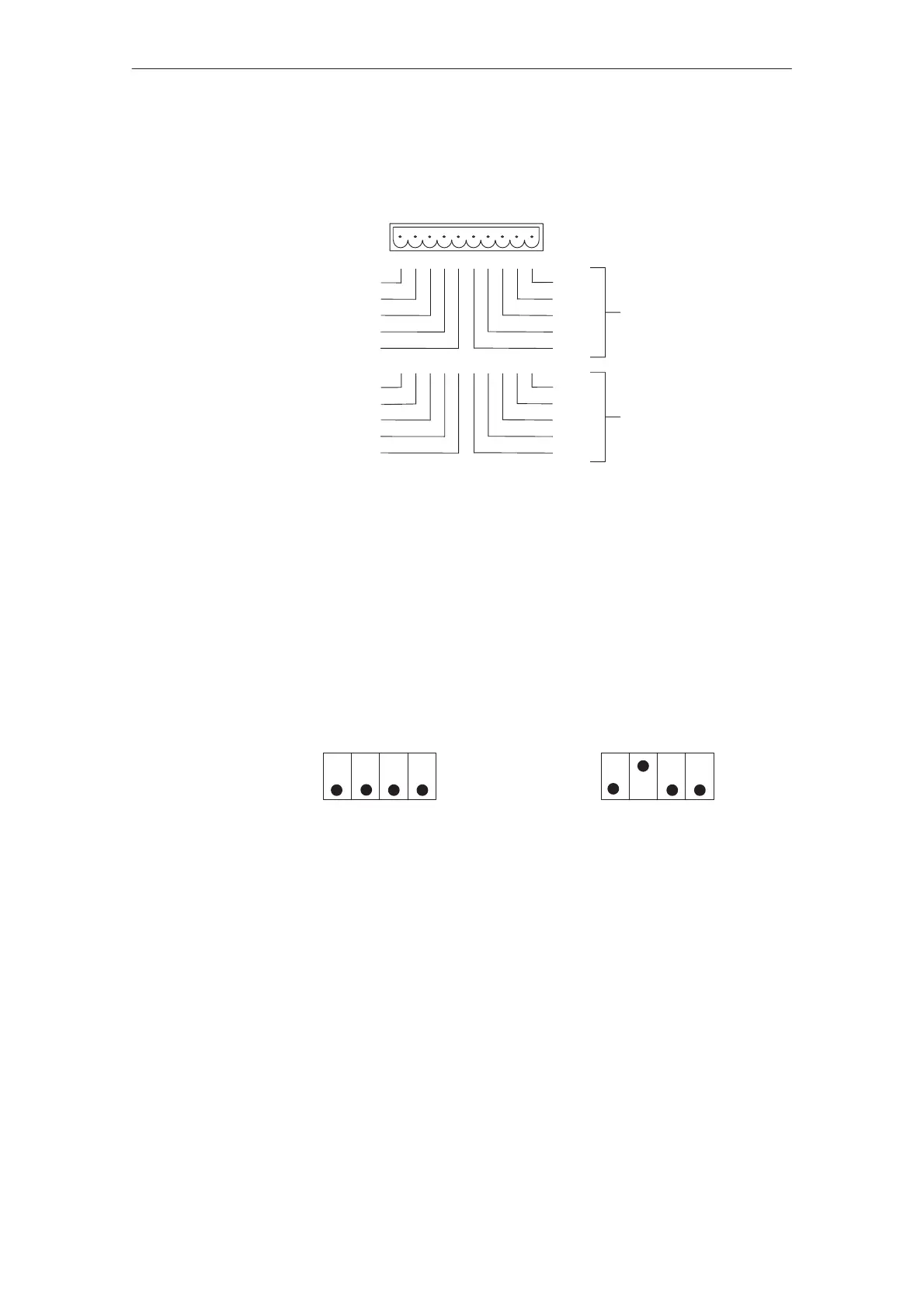
The DIL switches on the direct key modules DKMA and DKMB must be set as
follows:
OFF
ON
S1 S2 S3 S4
DKM A
S1 S2 S3 S4
DKM B
OFF
ON
S S1 must always be ON;
S S2 selects the module board (DKM A = ON, DKM B = OFF);
S S3 and S4 must be ON to drive the outputs.
Pin arrays
DIL switch
Options

 Loading...