Appendix Motherboard
A.2 Internal Connector
SIMATIC IPC527G
Operating Instructions, 03/2019, A5E45491226-AA
103
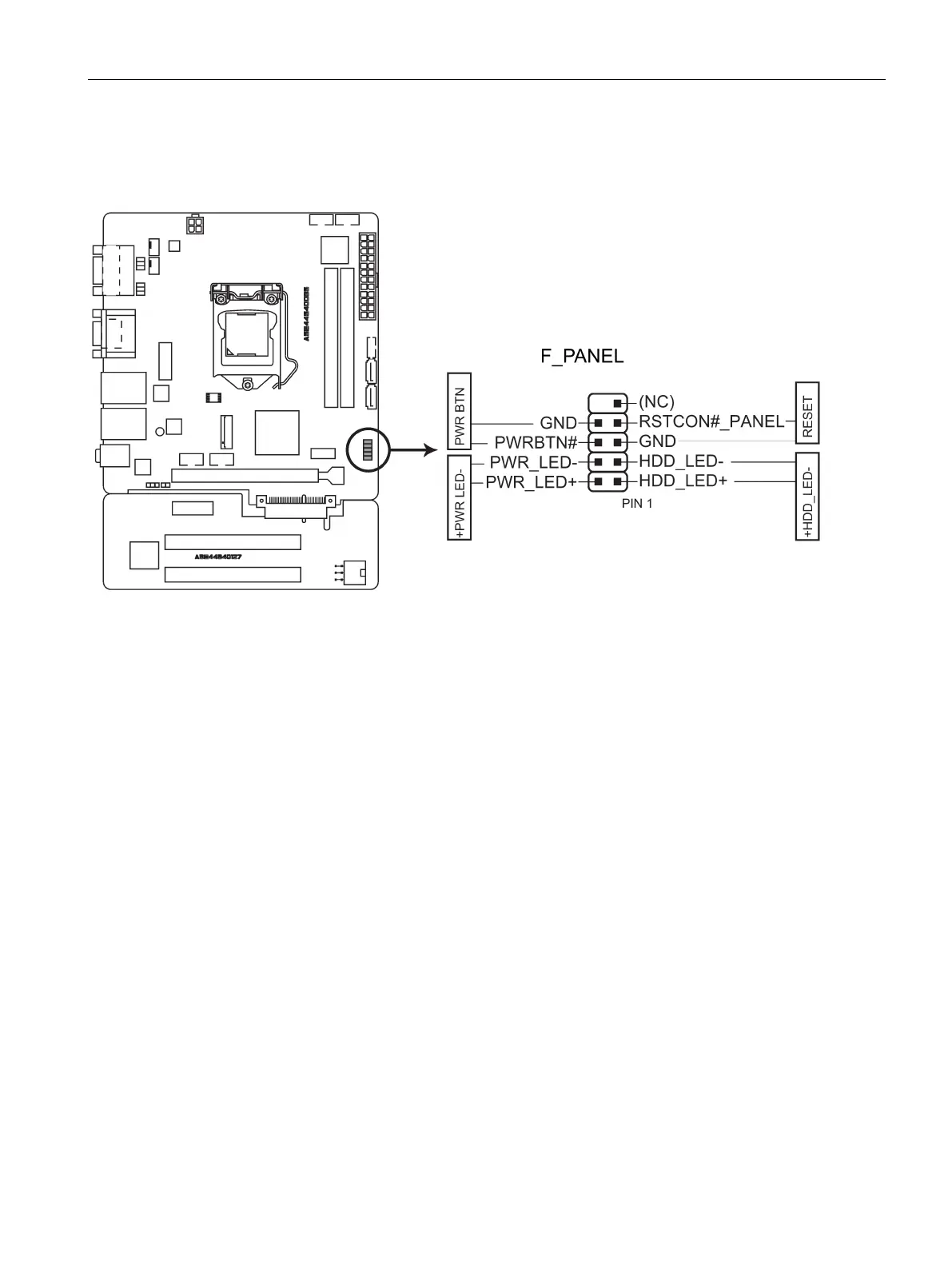
System panel connector (F_PANEL)
This connector supports several chassis-mounted functions.
System power LED (2-pin PWR_LED)
This 2-pin connector is for the system power LED. Connect the chassis power LED cable to
this connector. The system power LED lights up when you turn on the system power, and
blinks when the system is in sleep mode.
Hard disk drive activity LED (2-pin HDD_LED)
This 2-pin connector is for the HDD Activity LED. Connect the HDD Activity LED cable to this
connector. The HDD LED lights up or flashes when data is read from or written to the HDD.
ATX power button/soft-off button (2-pin PWR_BTN)
This connector is for the system power button.
Reset button (2-pin RESET)
This 2-pin connector is for the chassis-mounted reset button for system reboot without
turning off the system power.
 Loading...