Technical information
8.4 Technical specifications
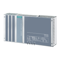
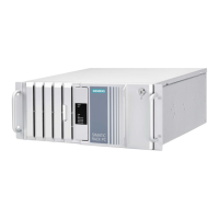
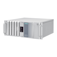
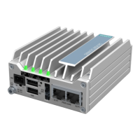
SIMATIC IPC677D
122 Operating Instructions, 09/2014, A5E32995420-AC
Electromagnetic compatibility
EN 61000-6-3, EN 61000-6-4, CISPR22 class A; FCC class A
Immunity with regard to
conducted interference on the
± 2 kV according to IEC 61000-4-4; burst
± 1 kV according to IEC 61000-4-5; symmetrical surge
± 2 kV according to IEC 61000-4-5; asymmetrical surge
Noise immunity on signal
lines
± 1 kV to IEC 61000-4-4; Burst; Length < 3 m
± 2 kV in accordance with IEC 61000-4-4; Burst; length > 3 m
± 2 kV in accordance with IEC 61000-4-5; Surge; length > 30 m
Immunity to electrostatic
± 6 kV contact discharge in accordance with IEC 61000-4-2
± 8 kV air discharge in accordance with IEC 61000-4-2
Immunity to RF interference 10 V/m 80 MHz - 2 GHz, 80% AM according to IEC 61000-4-3
3 V/m 2–2.7 GHz, 80% AM according to IEC 61000-4-3
10 V 10 KHz–80 MHz, 80% AM according to IEC 61000-4-6
Immunity to magnetic fields
100 A/m, 50/60 Hz according to IEC 61000-4-8
Processor
• Intel Xeon E3-1268L v3 2.3 (3.3) GHz, 4 cores, 8 threads, GT2,
8 MB second level cache, AMT
• Intel Core i3-4330TE 2.4 GHz, 2 cores, 4 threads, GT2, 3 MB
second level cache, AMT
• Intel Celeron G1820TE 2.2 GHz, 2 cores, 2 threads, GT1, 2 MB
second level cache
Main memory Expansion options
• 2 GB, 4 GB, 8 GB, 16 GB without ECC
• 4 GB, 8 GB, 16 GB with ECC
Expansion card slots 1 × PCI 185 mm long and 1 × PCI 185 mm long
1 × PCI 185 mm long and 1 × PCIe x16 185 mm long
1 × PCIe x16 185 mm long and 1 × PCIe x4 185 mm long
Hard disk drive 1 × 3.5" SATA HD
1 × 2.5" SATA SSD, ≥ 240 GB standard
DVD burner
∗2
Serial ATA, See order documentation for features
Restriction for DVD burner drives: 10 to 58 Hz: 0.019 mm / 58 to 500 Hz: 2.5 m/s
2
Burner can only be operated in an interference-free environment