Electrical connection
6.2 Connecting the machine
1LA5/6/7/9, 1LG4/6, 1MA6/7, 1MB..1/2/3/4/5 - SH 63 ... 355
Operating Instructions, 06/2018, A5E44455710A
71
Circuit diagram inside the terminal box cover
Data on the connection and connecting the machine winding can be found in the circuit
diagram in the cover of the terminal box.
The standard motors are suitable for clockwise and counter-clockwise rotation.
For defined directions of rotation (direction of rotation arrow), appropriately connect the line
power cables.
● If you connect the line cables with phase sequence L1, L2, L3 at U, V, W or according t
o
N
EMA at T
1
T
2
T
3
, then the machine rotates in the clockwise direction.
● If you interchange two connections, e.g. L1, L2, L3 at V, U, W or according to NEMA at
T
2
T
1
T
3
, then the machine rotates counter-clockwise.
According to IEC According to NEMA
1
2
3
Counter-clockwise
rotation
V U W T
2
T
1
T
3
Direction of rotation of the motor when looking at DE
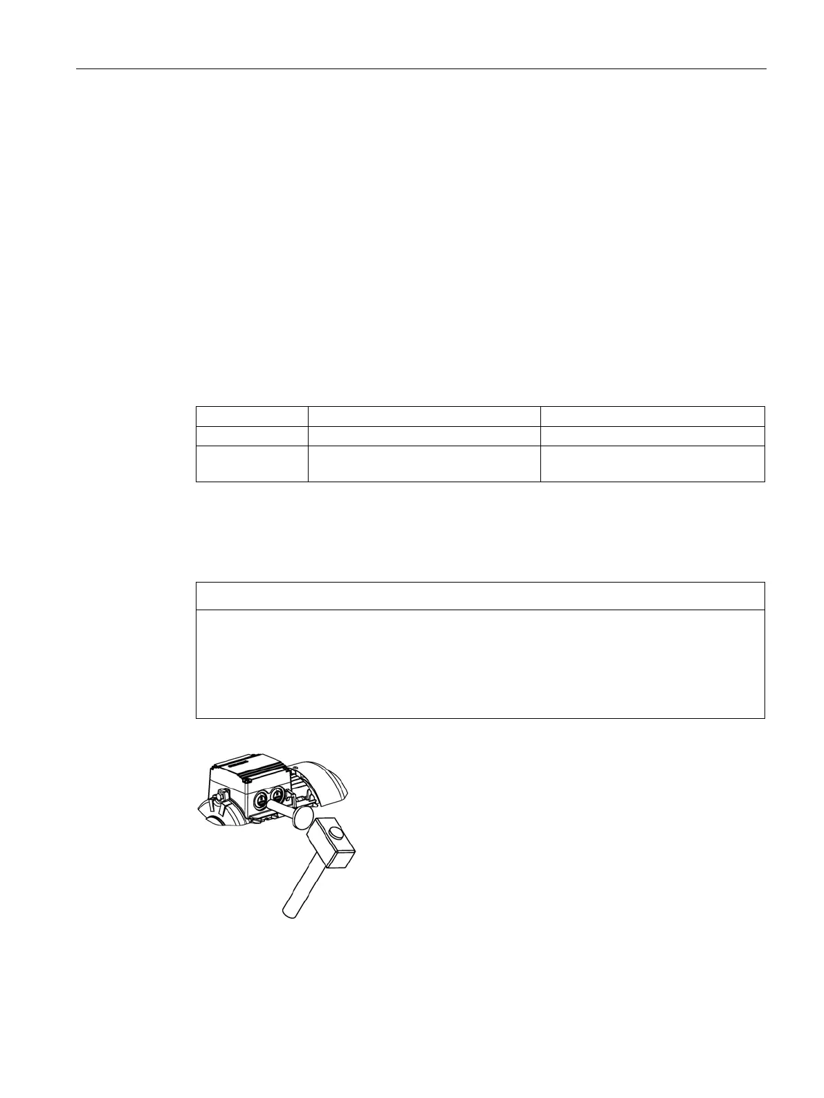
Damage to the terminal box
To avoid damaging the terminal box:
• Knockout openings in the terminal box must be knocked out using appropriate methods.
• Do not damage the terminal box, the terminal board, the cable connections etc. insi
de
t
he terminal box.
 Loading...


