3.3.2.1 Design of the thyristor stack
Thyristor double stack
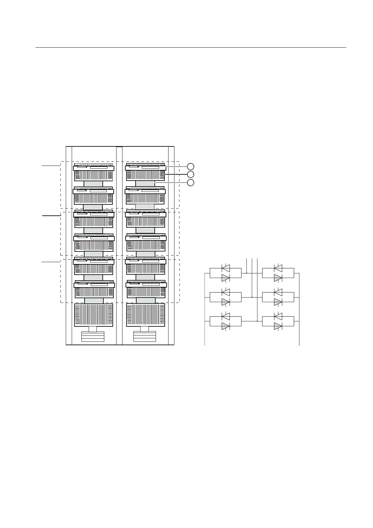
The thyristor double stack in a (B6C)A(B6C) connection is the core of the power unit cabinet.
A double stack comprises two clamped assemblies, each with six phase control thyristors and
seven heat sinks. Each thyristor has its own thyristor electronics board.
8
9
:
9
:8
U Phase U ① Thyristor electronics board (12x)
V Phase V ② Heat sink (14x)
W Phase W ③ Thyristor (12x)
Figure 3-2 Thyristor double stack
The thyristors assigned to one conduction direction are divided between two clamped
assemblies. The distribution across two clamped stacks ensures optimum cooling and
simplifies the busbar arrangement.
RC circuit
Pairs of anti-parallel thyristors are protected by an RC snubber circuit. The capacitors are
mounted on the thyristor double stack. The resistors are installed under the fan.
Description
3.3 Power unit
SINAMICS SL150 6SL38600UL432AA0Z
Operating Instructions Rev.201910281433 EXAMPLE 29

 Loading...


