The RC circuit limits the rate of voltage rise and voltage overshoot when the thyristors are
turned off.
Thyristor electronics
Each thyristor has its own thyristor electronics board. This module is used to fire the thyristors.
The RC snubber circuit supplies the thyristor electronics with power.
3.3.2.2 Coupling unit for ground fault sensing
The device is operated on an ungrounded IT line system. Insulation faults must therefore be
detected. A system comprising two parts is employed to detect insulation faults:
● The AGH... coupling device
● The IRDH275... evaluation unit
The coupling device couples the voltage to be monitored and limits the measuring current in the
event of a fault.
The coupling unit is connected upstream of the A‑ISOMETER IRDH275... in the closed-loop
control cabinet.
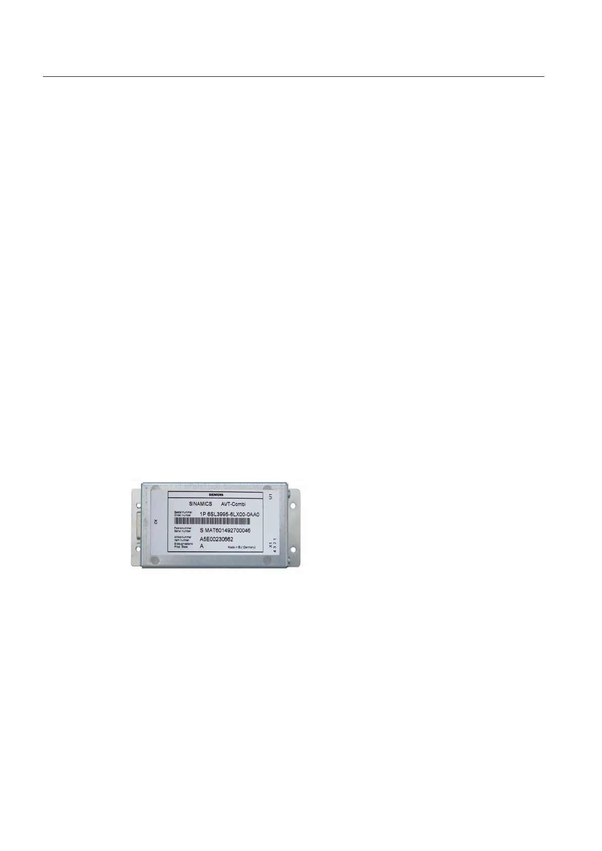
3.3.2.3 AVT combination module
The AVT combination module (Actual Value Transmission) processes signals for sensing the
actual current and voltage values. The AVT combination module converts analog signals into
digital signals. Then the module transfers the signals to the Power Stack Adapter (PSA). The
signals are transferred to the PSA via fiber-optic cables.
Figure 3-3 AVT combination module
See also
Voltage actual value sensing (Page 36)
Replacing the AVT combination module (Page 88)
Description
3.3 Power unit
SINAMICS SL150 6SL38600UL432AA0Z
30 Operating Instructions Rev.201910281433 EXAMPLE

 Loading...


