HBD-DZ170/DZ171/DZ175/DZ310/DZ510/DZ610/DZ810
11
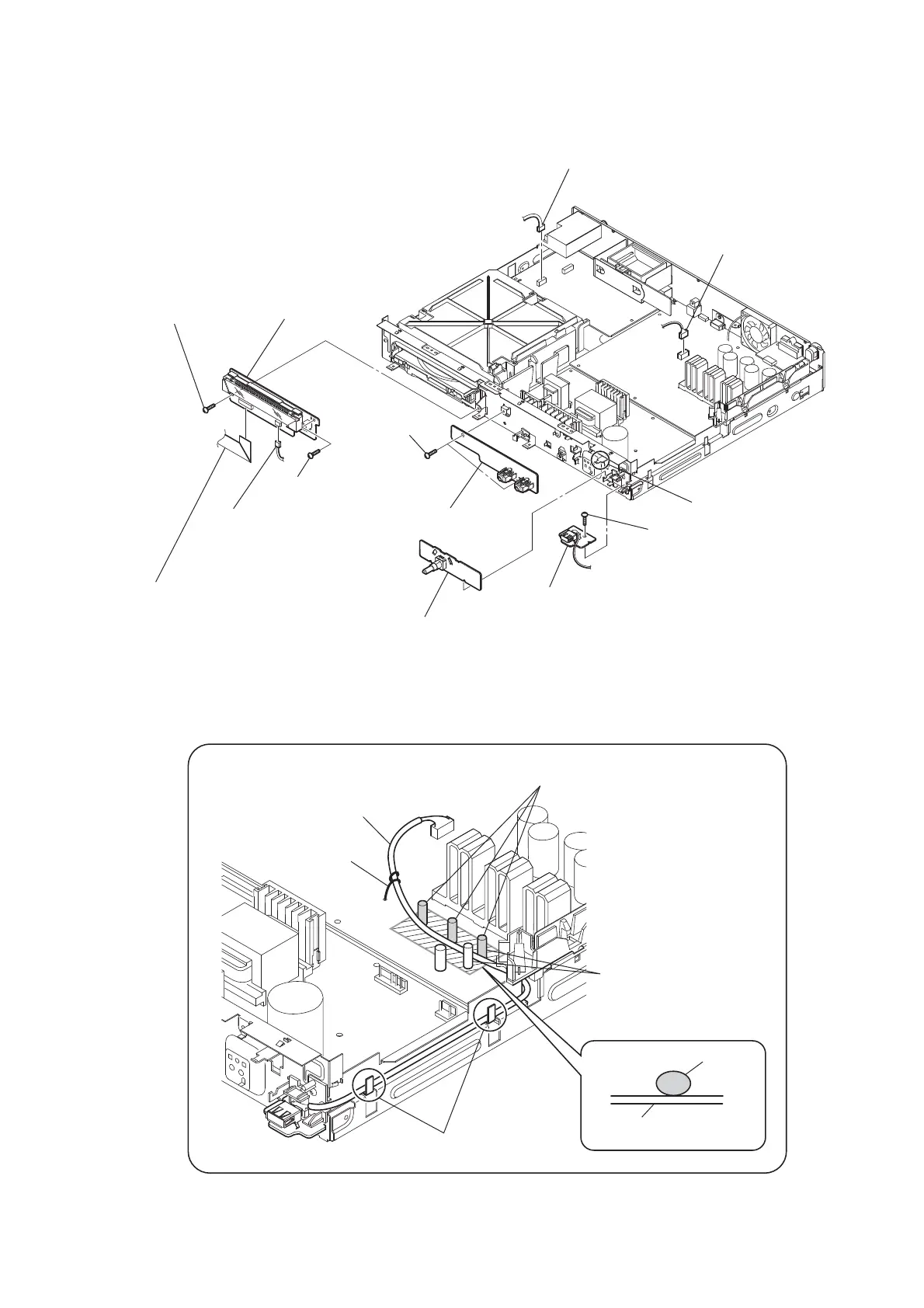
2-4. FL BOARD, ENCODER BOARD, JACK BOARD, USB BOARD
1 wire (flat type) (13 core) (CN5005)
(DZ170/DZ171/DZ175)
wire (flat type) (15 core) (CN5002)
(DZ310/DZ510/DZ610/DZ810)
2 screw
(+BV3 (3-CR))
3 screw
(+BV3 (3-CR))
qs screw
(+BV3 (3-CR))
9 two screws
(+BV3 (3-CR))
4 CN5006 (2P)
(DZ170/DZ171/DZ175)
CN5007 (3P)
(DZ310/DZ510/DZ610/DZ810)
8 CN4007 (4P) (DZ170/DZ171/DZ175)
CN4008 (5P) (DZ310/DZ510/DZ610/DZ810)
5 FL board
0 JACK board
qd JACK board
MAIN board
7 ENCODER board
6 claw
qa CN2101 (5P)
Arranging the USB wire
USB wire
USB wire
Tie up with LP501.
Thread the USB wire through
the capacitors.
The USB wire should be located on the front side
from these capacitors.
Dress the USB wire in this area
properly along the board.
Have the USB wire spread on the inside
of the claws of the chassis.
 Loading...