HBD-DZ170/DZ171/DZ175/DZ310/DZ510/DZ610/DZ810
14
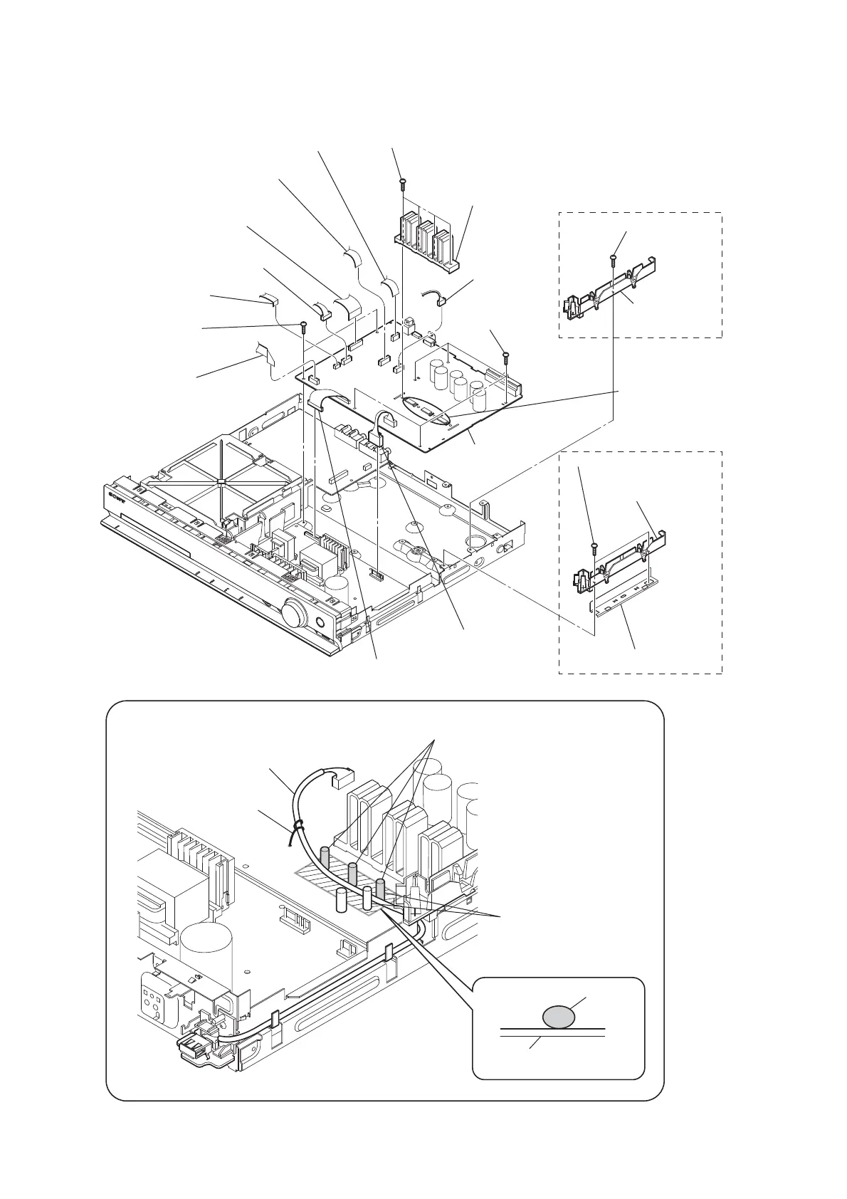
2-8. MAIN BOARD
MAIN board
4 CN2101 (5P)
qh heat sink
8 CN1501 (6P)
1 wire (flat type) (13 core) (CN507)
(DZ170/DZ171/DZ175)
wire (flat type) (15 core) (CN506)
(DZ310/DZ510/DZ610/DZ810)
6 wire (flat type) (9 core) (CN472)
7 wire (flat type) (17 core) (CN503)
(DZ170/DZ171/DZ175)
wire (flat type) (19 core) (CN504)
(DZ310/DZ510/DZ610/DZ810)
5 wire (flat type) (24 core) (CN1101)
9 wire (flat type) (5 core)
(CN1502)
2 CN906 (11P)
3 CN904 (5P)
0 two screws
(+BV3 (3-CR))
qd screw
(+BV3 (3-CR))
qg four screws
(+BV3 (3-CR))
qj five screws
(+BV3 (3-CR))
qk two screws
(+BV3 (3-CR))
ql MAIN board
EXCEPT US, CND, SP, EA
US, CND, SP, EA
qa insulated plate
(PC-DSZ)
qf insulated plate
(PC-DSZ)
qs shield plate (PC-DSZ)
Arranging the USB wire
USB wire
USB wire
Tie up with LP501.
Thread the USB wire through
the capacitors.
The USB wire should be located on the front side
from these capacitors.
Dress the USB wire in this area
properly along the board.
When the heat sink
has been removed,
apply oil compound
(G-747) to it.
 Loading...