Installation Diagram
FfQOf:lnsta!iatiOn(Ftq
...
tli:Jroj~cti()n
),
'I.'
. ":
;-
:
,_
.:"'''''.
_.~":.
v
.;:
;
,p
.,-
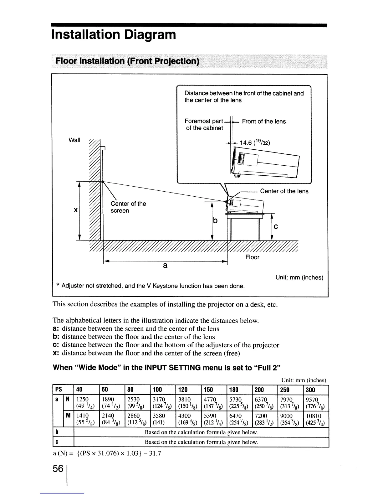
Distance between the front of the cabinet and
the center of the lens
Wall
x
a
Foremost part
of the cabinet
Front of the lens
//////%
Floor
Unit: mm (inches)
*Adjuster not stretched, and the V Keystone function has been done.
This section describes the examples
of
installing the projector on a desk, etc.
The alphabetical letters
in
the illustration indicate the distances below.
a:
distance between the screen and the center
of
the lens
b:
distance between the floor and the center
of
the lens
C:
distance between the floor and the bottom
of
the adjusters
of
the projector
x:
distance between the floor and the center
of
the screen (free)
When "Wide Mode"
in
the INPUT SETTING menu is set to "Full 2"
Unit: mm (inches)
PS
40
60
80
100
120
150
180
200
250
300
a N
1250
1890
2530
3170 3810
4770
5730
6370
7970
9570
(49
1
/
4
)
(74
'/
2
)
(99
5
/
8
)
(124
7
/
8
)
(150
1
/
8
)
(l87
7
/g)
(225
5
/
8
)
(250
7
/
8
)
(313
7
1
8
)
(376
7
/g)
M
1410
2140 2860
3580
4300
5390
6470 7200
9000
lO8lO
(55
5
/
8
)
(84
3
/
8
)
(1I2
5
/g)
(141)
(169
3
/
8
)
(212
1
/
4
)
(254
7/
8
)
(283
1
/
2
)
(354
3
/
8
)
(425
\)
b
Based on the calculation formula given below.
C
Based on the calculation formula given below.
a (N) = {(PS x 31.076) x 1.03} - 31.7
56
 Loading...