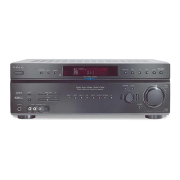
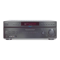
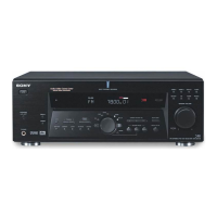
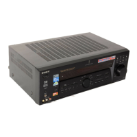
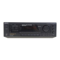
STR-DE695
2424
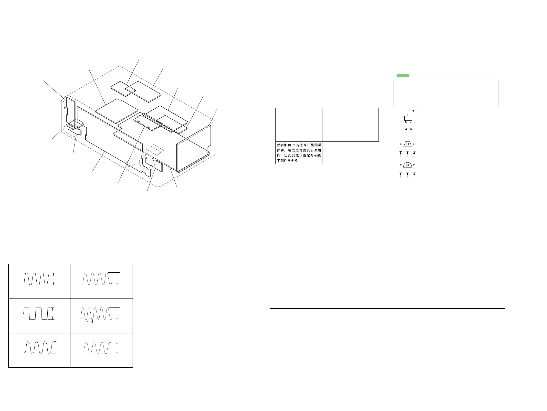
4-7. CIRCUIT BOARDS LOCATION
MAIN board
VOL board
STANDBY board
VIDEO board
S-VIDEO board
SPEAKER board
AC SELECT board (E2, E3, Tourist model only)
DIGITAL boar
POWER board
HEADPHONE board
VIDEO3 board
DISPLAY board
SB AMP board
(US, Canadian
model only)
Ver 1.1
• Waveforms (DIGITAL Board)
3.4Vp-p
1
IC1301
qd
(CKOUT)
1V/DIV 50nsec/DIV
12.288MHz
3.4Vp-p
2
IC1301
qf
(BCK)
1V/DIV 0.2µsec/DIV
3.07MHz
3.2Vp-p
3
IC1301
wa
(XOUT)
1V/DIV 50nsec/DIV
12.288MHz
3.2Vp-p
4
IC1501
qs
(MCLK2)
1V/DIV 50nsec/DIV
13.5MHz
4.0Vp-p
5
IC1501
qf
(SCKOUT)
1V/DIV 20nsec/DIV
40nsec
3.2Vp-p
6
IC1101
tj
(X1)
1V/DIV 20nsec/DIV
16.5MHz
THIS NOTE IS COMMON FOR PRINTED WIRING
BOARDS AND SCHEMATIC DIAGRAMS.
(In addition to this, the necessary note is
printed in each block.)
for schematic diagram:
• All capacitors are in µF unless otherwise noted. pF: µµF
50 WV or less are not indicated except for electrolytics
and tantalums.
• All resistors are in Ω and
1
/
4
W or less unless otherwise
specified.
•
f
: internal component.
• 2 : nonflammable resistor.
• 5 : fusible resistor.
• C : panel designation.
• A : B+ Line.
• B : B– Line.
•Voltage and waveforms are dc with respect to ground
under no-signal (detuned) conditions.
no mark : FM
•Voltages are taken with a VOM (Input impedance 10 MΩ).
Voltage variations may be noted due to normal produc-
tion tolerances.
•Waveforms are taken with a oscilloscope.
Voltage variations may be noted due to normal produc-
tion tolerances.
• Circled numbers refer to waveforms.
• Signal path.
F : TUNER (FM/AM)
L : VIDEO (AUDIO)
I : VIDEO
J : CD (ANALOG)
c : CD (DIGITAL)
•Abbreviation
CND : Canadian model.
AUS: Australian model.
CH : Chinese model.
TW : Taiwan model.
SP : Singapore model.
MY : Malaysia model.
AR : Argentina model.
E2 : AC 120 V area in E model.
E3 : AC 240 V area in E model.
JE : Tourist model.
MX : Mexican model.
for printed wiring boards:
• X : parts extracted from the component side.
•
f
: internal component.
• : Pattern from the side which enables seeing.
Caution:
Pattern face side: Parts on the pattern face side seen from the
(Side B) pattern face are indicated.
Parts face side: Parts on the parts face side seen from the
(Side A) parts face are indicated.
C
B
These are omitted.
E
Q
B
These are omitted.
C
Q
Q
E
BCE
Note:
The components identi-
fied by mark 0 or dotted
line with mark 0 are criti-
cal for safety.
Replace only with part
number specified.
Note:
Les composants identifiés par
une marque 0 sont critiques
pour la sécurité.
Ne les remplacer que par une
piéce portant le numéro
spécifié.
•Abbreviation
CND : Canadian model.
AUS: Australian model.
CH : Chinese model.
TW : Taiwan model.
SP : Singapore model.
MY : Malaysia model.
AR : Argentina model.
E2 : AC 120 V area in E model.
E3 : AC 240 V area in E model.
JE : Tourist model.
MX : Mexican model.
 Loading...