5
TABLE OF CONTENTS
1. GENERAL
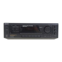
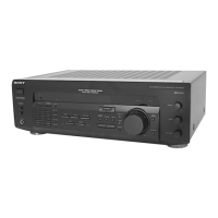
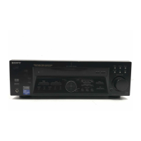
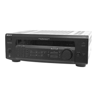
Main unit ................................................................................. 6
Remote button description....................................................... 7
2. DISASSEMBLY
2-1. Case ..................................................................................... 9
2-2. Front Panel Section ........................................................... 10
2-3. Back Panel......................................................................... 10
2-4. Digital Board ..................................................................... 11
2-5. Standby Board ................................................................... 11
2-6. Main Board ....................................................................... 12
2-7. SB AMP Board (US, Canadian model only)..................... 12
3. TEST MODE ...................................................................... 13
4. DIAGRAMS
4-1. IC Pin Descriptions ........................................................... 14
4-2. Block Diagram – Tuner/Audio Section –.......................... 19
4-3. Block Diagram – Digital Section – ................................... 20
4-4. Block Diagram – Key/Display Section – .......................... 21
4-5. Block Diagram – Video Section – ..................................... 22
4-6. Block Diagram – Power Section – .................................... 23
4-7. Circuit Boards Location .................................................... 24
4-8. Printed Wiring Boards – Main Section – .......................... 25
4-9. Schematic Diagram – Main Section (1/3) – ...................... 26
4-10. Schematic Diagram – Main Section (2/3) – ...................... 27
4-11. Schematic Diagram – Main Section (3/3) – ...................... 28
4-12. Schematic Diagram – Digital Section (1/3) – ................... 29
4-13. Schematic Diagram – Digital Section (2/3) – ................... 30
4-14. Schematic Diagram – Digital Section (3/3) – ................... 31
4-15. Printed Wiring Board – Digital Section (1/2) – ................ 32
4-16. Printed Wiring Board – Digital Section (2/2) – ................ 33
4-17. Printed Wiring Boards – Video Section – ......................... 34
4-18. Schematic Diagram – Video Section – .............................. 35
4-19. Printed Wiring Board – S-video Section – ........................ 36
4-20. Schematic Diagram – S-video Section –........................... 37
4-21. Printed Wiring Boards – Speaker Section – ...................... 38
4-22. Schematic Diagram – Speaker Section – .......................... 39
4-23. Printed Wiring Boards – Display Section – ...................... 40
4-24. Schematic Diagram – Display Section –........................... 41
4-25. Printed Wiring Boards – Power Section – ......................... 42
4-26. Schematic Diagram – Power Section – ............................. 43
4-27. IC Block Diagrams............................................................ 44
5. EXPLODED VIEWS
5-1. Case Section ...................................................................... 47
5-2. Front Panel Section ........................................................... 48
5-3. Chassis Section-1 .............................................................. 49
5-4. Chassis Section-2 .............................................................. 50
6. ELECTRICAL PARTS LIST......................................... 51
STR-DE695
Ver 1.1
 Loading...