EasyManua.ls Logo

Sony STR-DE695 Service Manual

Sony STR-DE695
68 pages
To Next Page IconTo Next Page
To Previous Page IconTo Previous Page
Page #41 background imageLoading...
Page #41 background image
STR-DE695
41 41
4-24. SCHEMATIC DIAGRAM — DISPLAY SECTION — • Refer to page 24 for Common Note on Schematic Diagram.
(Page 31)
C100
C132
C133
C134
C135
C136
C137
C138
C139
C140
C141
C142
C143
R150
R153
S100 S101 S102 S103 S104
S110 S111 S112 S113 S114 S115
S120S121S122S123S124S125
S130S131S132S133S134S135
L103
S116
S126
R141
D103D104D105
S151S152
S107
S117
R142
C157
R160
R161
R101
R111
R121
R131
R102 R103
R112 R113
R122R123
R132R133
R104
R114
R134
R105
R115
R125
R135
R162
R116
R136
L102
R172
R173
R174
R126
R117
R106 R107
R124
R163
D102
C112
C111
C110
C101
C109
C108
C151
C144
C114
C105
C155
C156
C104
D106
CNS100
IC102
R199
R198
FL101
R154
IC100
CN101CNP102
RV102
RV101
L101
Q101Q100
CNP104 CN103
IC101
C115
R175
C150
D101

Other manuals for Sony STR-DE695

Question and Answer IconNeed help?

Do you have a question about the Sony STR-DE695 and is the answer not in the manual?

Sony STR-DE695 Specifications

General IconGeneral
Dimensions (WxDxH)430 x 310 x 157 mm
Power requirements230 V; 50/60 Hz
Supported radio bandsFM, MW
Radio Data System (RDS)Yes
I/O ports5.1 Analogue Input - 1.0 Audio Input - 3.0 Audio Input Front - 1 Audio Output - 1.0 Control A1 / A1 II Digital Input: coaxial - 1.0 Digital Input: optical - 3.0 Digital Output: optical - 1.0 Headphone Output Monitor Output (Picture): FBAS - 1.0 Monitor Output (Picture): S-Video - 1.0 Speaker Selector A, B, A+B S-Video Input - 3.0 S-Video Output- 1.0 Video Input - 4.0 Video Output - 1.0
Connectivity technologyWired
Power consumption (standby)0.3 W
Power consumption (typical)250 W
Weight and Dimensions IconWeight and Dimensions
Weight8500 g

Summary

Specifications

Audio Power Specifications

Details on power output and total harmonic distortion for various load conditions.

Safety Check-Out

Leakage Test

Procedure for checking AC leakage current from exposed metal parts to earth ground.

Section 2 Disassembly

Section 3 Test Mode

Section 4 Diagrams

4-1. IC Pin Descriptions

Detailed pin descriptions for ICs used in the digital board.

4-2. Block Diagram - Tuner/Audio Section

Block diagram illustrating the signal flow of the tuner and audio sections.

4-9. Schematic Diagram - Main Section (1/3)

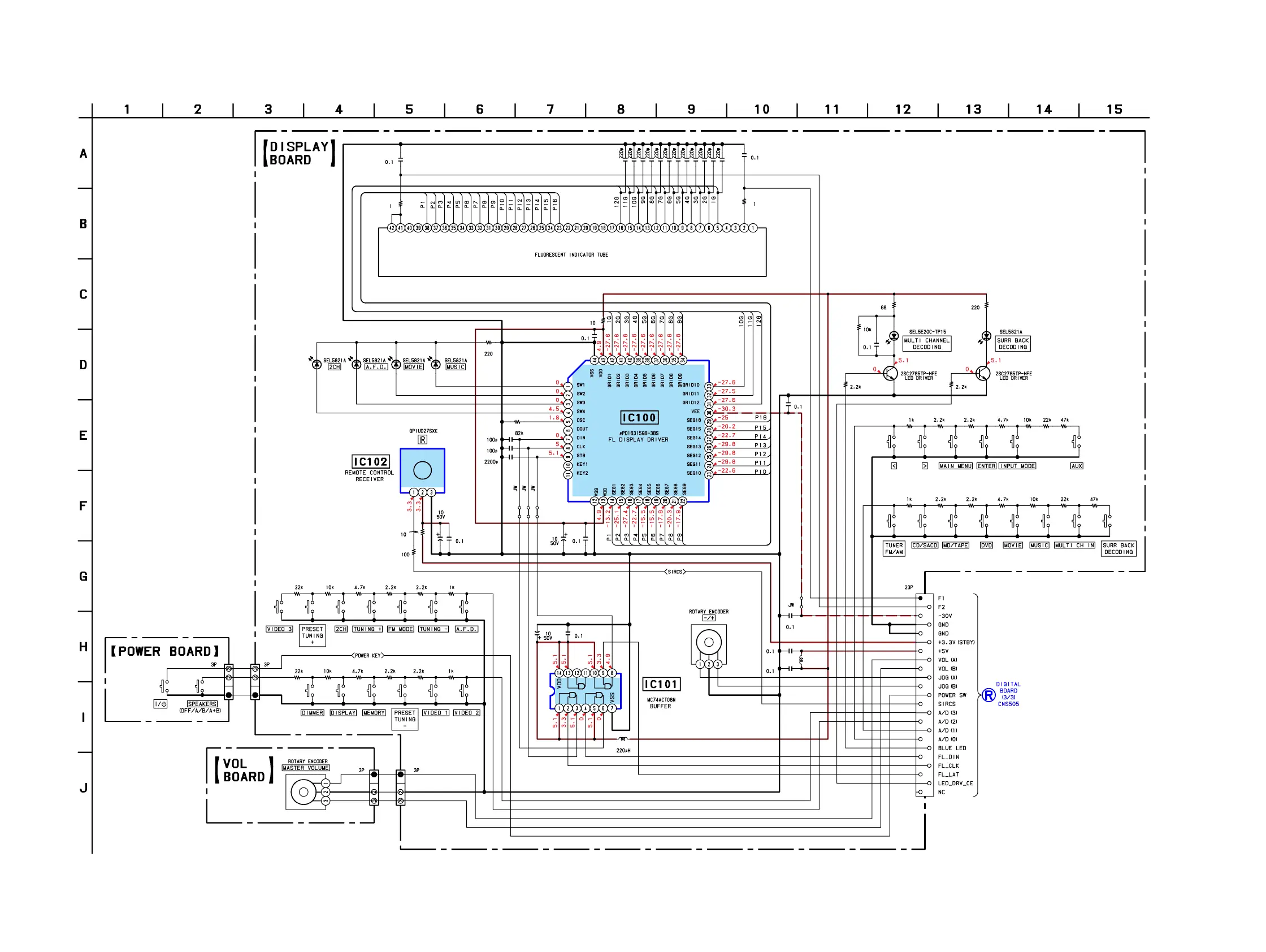
Schematic diagram of the main board, part 1 of 3.

4-15. Printed Wiring Board - Digital Section (1/2)

Printed wiring board layout for the digital section, part 1 of 2.

4-18. Schematic Diagram - Video Section

Schematic diagram illustrating the video signal processing circuitry.

4-22. Schematic Diagram - Speaker Section

Schematic diagram detailing the speaker output and protection circuitry.

4-25. Printed Wiring Boards - Power Section

Printed wiring board layout for the power supply section.

4-27. IC Block Diagrams

Block diagrams illustrating the internal logic of key ICs.

Section 6 Electrical Parts List

Related product manuals