Edition Manual Chapter Page
2014-09-20 Workshop Manual, GGP Park 4 Hydraulic system 5
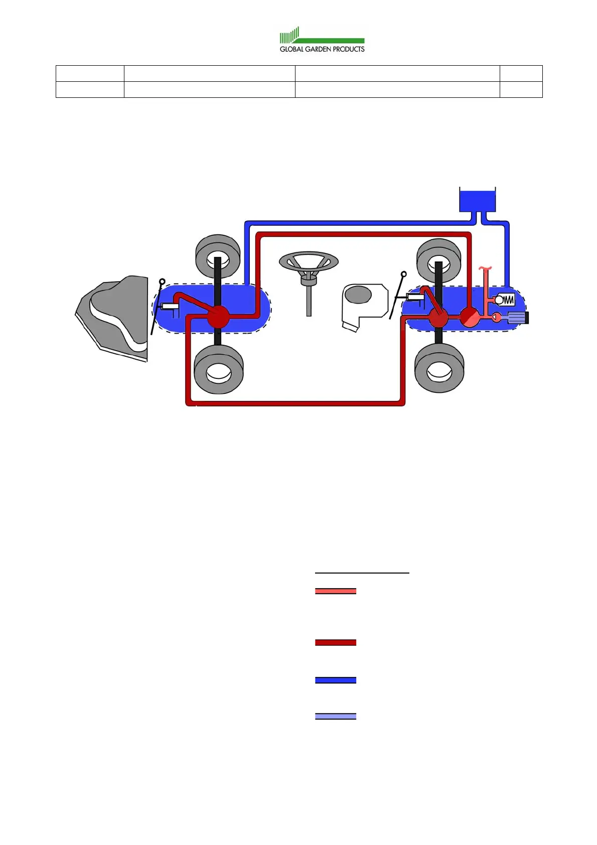
4.3 Hydraulic pump integrated in the rear axle drive
4.3.1 Physical description
B. Front axle drive. The parts 9 and 10
below are built in the front axle drive.
9. Hydraulic motor, front axle.
10. By-pass valve, front axle.
11. Leak flow line.
12. Main flow line.
13. Main flow line.
Colour - Pressure
Red is the feeding pressure to the
main pump and to the external
hudraulics.
Dark red is the working pressure
to the hydraulic motors.
Blue is the atmospheric pressure
in the oil container and housings.
Light blue is below the
atmospheric pressure (pump
suction side).
A. Rear axle drive.
The parts 1-3 and 5-8 below are built
in the rear axle drive.
1. Charge pump, 35-45 bar.
2. Main pump.
3. Pressure limit valve for the charge
pressure.
4. Oil container.
5. Oil filter.
6. Connection to the external hydraulics
(steering converter and implement
lifter).
7. Hydraulic motor, rear axle.
8. By-pass valve, rear axle.
1
B
A
9
10
2
7
3
4
5
6
8
11
13
12
1
 Loading...