Edition Manual Chapter Page
2014-09-09 Workshop Manual, GGP Park 6 Control wires 16
6.6 Replacement of PTO wire
6.6.1 Machines with the control panel
to the right
This procedure is valid for machines with the
control panel to the right of the operator, e.g.
Comfort, Royal, Senator etc.
Dismantling of PTO engagement wire
1. Remove the cover over the control panel.
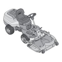
2. Release the wire from the tension spring at
the belt tensioner.
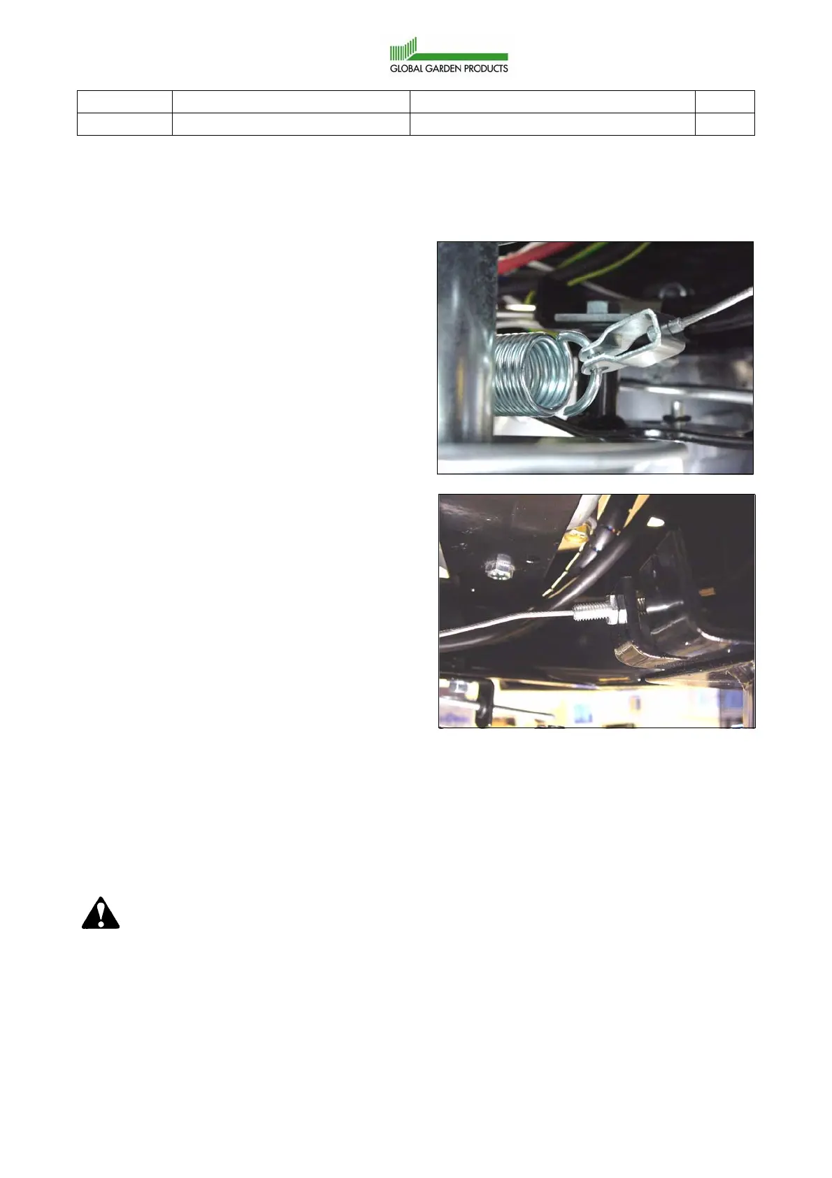
3. Release the nuts at the wire’s lower attach-
ment point, and dismantle the wire from
the support.
4. Release the nuts at the wire’s upper
attachment point, unhook the Z nipple from
the control arm, and remove the wire from
the machine.
Cut off the cable holder that holds the
cables and wires in the articulation point.
Notice how the wire is routed, since it sim-
plifies fitting if the new wire is routed in the
same way as the old one.
Assembly of PTO engagement wire
Assemble in the reverse order.
It is often easier to fit the wire from underneath,
since the Z nipple is easier to guide correctly
through the seat bracket than the spring attach-
ment in the bottom end of the wire.
Follow-up work
Warning!
The PTO brake is part of the ma-
chine’s safety system. It is therefore
especially important that it is
checked and adjusted correctly.
Adjust the wire and the PTO brake.
See “Adjustment of PTO wire and brake” at
page 18.
 Loading...