Edition Manual Chapter Page
2014-09-20 Workshop Manual, GGP Park 4 Hydraulic system 18
4.6 Hydraulic assisted steer-
ing
This section is valid for 2WD machines
(e.g. Park Ranger Svan).
4.6.1 Physical description
This section explanes the physical
arrangement of the hydraulic components and
the different pressures in the system.
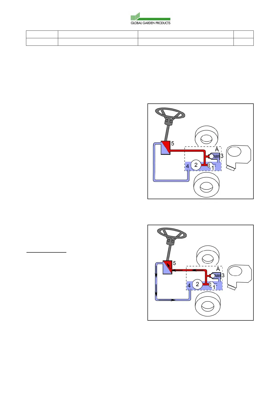
A. The dashed box indicates parts (1-4)
which are builtin the rear axle drive.
1. Charge pump.
2. Main pump. This pump belongs to the
driving system and supplies the oil
pressure/flow.
3. Pressure limit valve.
4. Oil container.
Red lines indicate the maximum total pressure
from the HST.
Blue lines indicate return oil with low pressure
(<1 bar).
4.6.2 Functional description
Steering wheel actuated
Operation state:
• Motor is running in full speed.
• The steering wheel is actuated.
The loading pump (1) is forcing oil through the
steering converter (5).
The oil flow is indicated with arrows in the figure
below. Since the steering converter (5) is
working, a pressure drop will be built up over it.
The pressure drop =
the pressure in the red line - the pressure after
the steering converter (5)
The pressure drop is depending on the steering
power needed and is limited of the built in valve
(3).
 Loading...