Edition Manual Chapter Page
2014-09-20 Workshop Manual, GGP Park 4 Hydraulic system 12
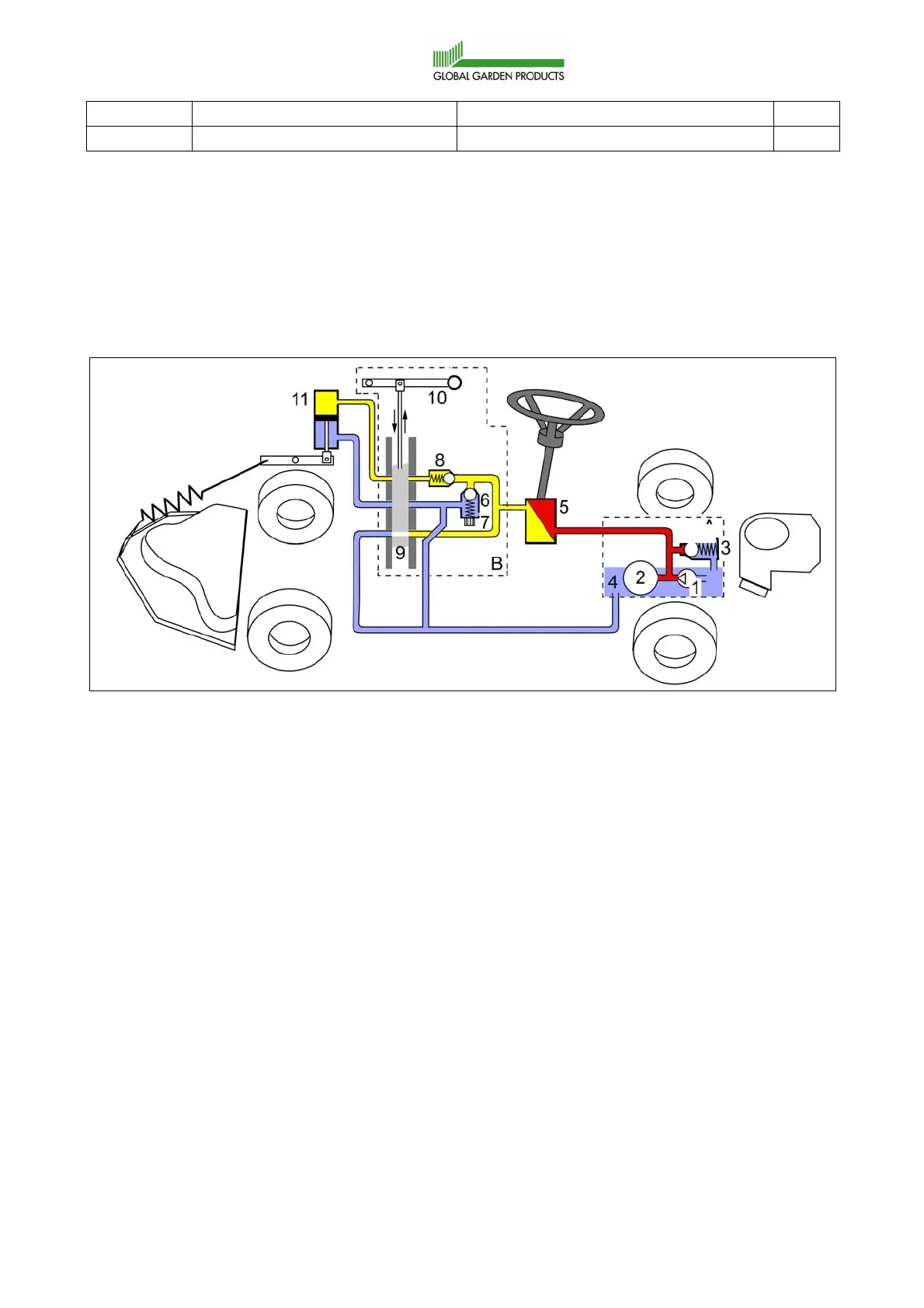
4.5 Hydraulic assisted steering and implement lifter
This section is valid for 4WD machines with steering chain.
4.5.1 Physical description
This section explanes the physical arrangement of the hydraulic components and the
different maximal pressures in the system.
A. The dashed box indicates parts (1-4)
which are builtin the rear axle drive or
arranged separat in front of the
engine.
B. Hand operated valve unit with the
built in parts 6-10.
1. Charge pump.
2. Main pump. This pump belongs to the
driving system and supplies the oil
pressure/flow.
3. Pressure limit valve.
4. Oil container.
5. Steering torque converter.
6. Pressure limit valve.
7. Pressure adjustment screw.
8. Non-return valve.
9. Slide with 4 different hole patterns for
the resp. functions. Illustrated in
normal status.
10. Hand lever, connected to the slide.
11. Double acting lifting cylinder.
Red lines indicate the maximum total
pressure from the HST when the torque
converter (5) works.
Yellow lines indicate the maximum
pressure to the lifting cylinder when it lifts
the implement.
Blue lines indicate return oil with low
pressure (>1 bar).
A
 Loading...