WORKSHOP MANUAL
T...102/122 - TC...102/122
Map of functional units
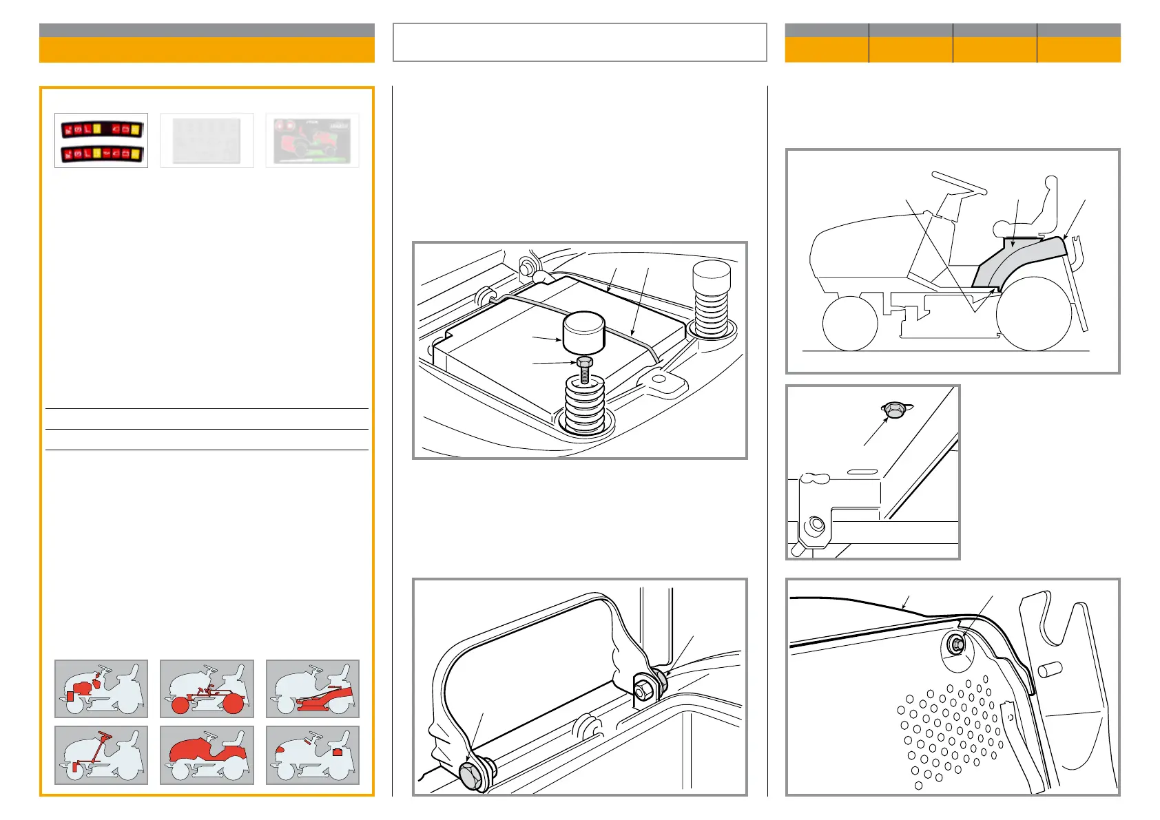
The cover (8) is xed by two screws (9) located un der
the side footboards and two screws (10) xing it to the
rear plate.
The cover (8) can be
removed after the cut-
ting height adjustment
lever has been set to its
highest position.
Remove the spring (1) xing the battery, ensuring that
accidental short circuits are not caused; rst discon-
nect the black cables (earth), then the red cable (posi-
tive) and remove the battery (2).
Remove the caps (5) from the springs and undo the
screws inside (6).
Remove the seat after having dismantled the two pins
(7).
Validity
General informations
Removing the wheel cover gives access to:
– the mount for the lever to raise the deck;
– the supports of the footboards.
Related topics
---
Tightening torques
9 Lower cover xing screw ...............4,0 ÷ 4,5 Nm
10 Upper cover xing screw ............ 4,0 ÷ 4,5 Nm
REMOVAL OF THE WHEEL COVER
CHAPTER REVISION FROM ... PAGE
5.2 0 2018 1 of 2
 Loading...