WORKSHOP MANUAL
T...102/122 - TC...102/122
Map of functional units
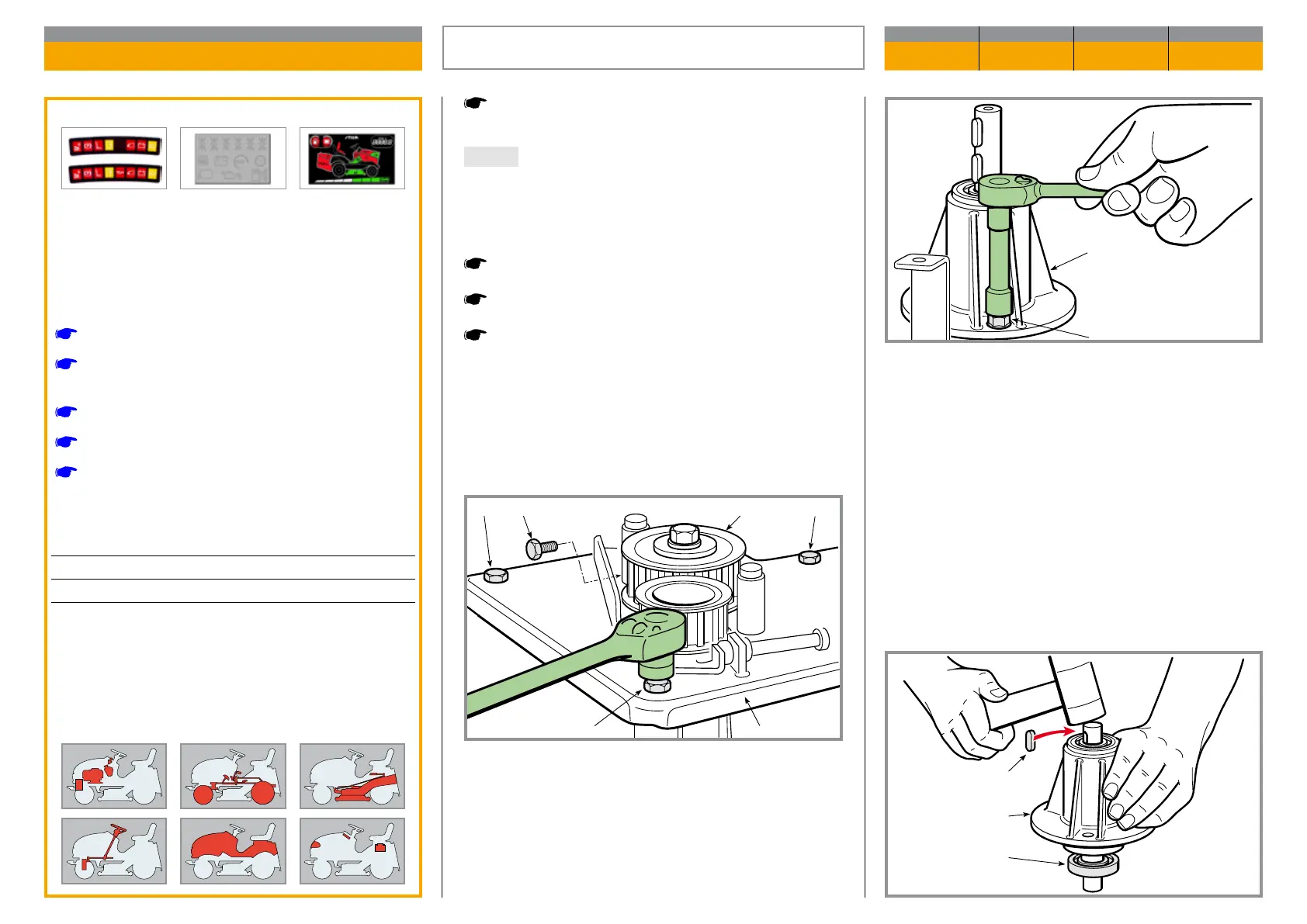
Dismantle the anged support (4) by unscrewing the
three xing screws (5).
The entire support (4), including shafts and bea rings,
is a spare part available as a single as sem bly unit.
If only the shaft or bearings are to be replaced, re mo-
ve the key or the two keys (6) and hit the shaft on the
pulley side with a plastic mallet to extract the shaft to-
gether with the lower bearing (7).
Remove the cutting deck.
NOTE This operation is not strictly necessary since,
with a lit tle practice and experience, it is possible to
dismantle the deck supports without removing the
cutting deck.
Remove the blade control belt.
Remove the blade connection belt.
Remove the blades and take o the hubs.
Extract the two toothed pulleys (1) from the blade
shafts, undo the seven screws (2) xing the plate (3)
and remove it.
Validity
General informations
Related topics
[
2.2] Special tools
[
4.9] Removing, sharpening and balancing the
blades
[
5.7] Removal of the cutting deck
[
6.6] Replacement of the blades control belt
[
6.7] Replacement of the blades connection belt
Tightening torques
2 Plate xing screws ......................... 30 ÷ 35 Nm
5 Flanged support xing nuts ............. 25 ÷ 30 Nm
REPLACEMENT OF THE SUPPORTS
AND SHAFTS OF THE BLADES
CHAPTER REVISION FROM ... PAGE
6.8 0 2018 1 of 2
 Loading...