WORKSHOP MANUAL
T...102/122 - TC...102/122
Map of functional units
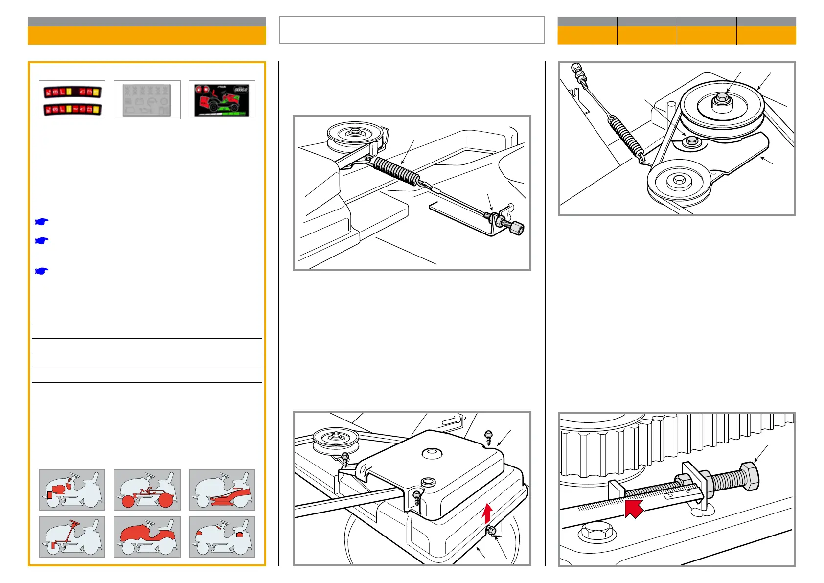
Record the reading on the adjuster (10) (this must
be reset at reassembly to give a preliminary belt ad-
justment) and slacken it o completely.
Dismantle the pin (11), slacken o the xing nuts of
the three pins (12) and the pulleys (13) and (14) to al-
low removal of the belt.
Set the cutting deck to the lowest position to obtain
greater access, then slacken o and uncouple the ad-
juster (1) to unload the spring (2) .
Dismantle the upper casing (3), undo screw (4) and
di smantle the control pulley (5); undo the articulation
screw (6) and remove the stretcher plate (7).
Remove the protection casing (8), slackening o the
six surround screws (9) and extract it from its slots.
Validity
General informations
Related topics
[
2.2] Special tools
[
4.1] Adjusting the engagement and checking
the blade brake
[
8.2] Belts assembly
Tightening torques
4 Blade pulley screws ....................... 20 ÷ 25 Nm
6 Stretcher plate articulation screw ... 35 ÷ 40 Nm
11-12 Pin xing nuts ......................... 30 ÷ 35 Nm
13-14 Pulley xing nuts ..................... 30 ÷ 35 Nm
REPLACEMENT OF THE
BLADES CONNECTION BELT
CHAPTER REVISION FROM ... PAGE
6.7 0 2018 1 of 2
 Loading...