11034, 036, 036 QS
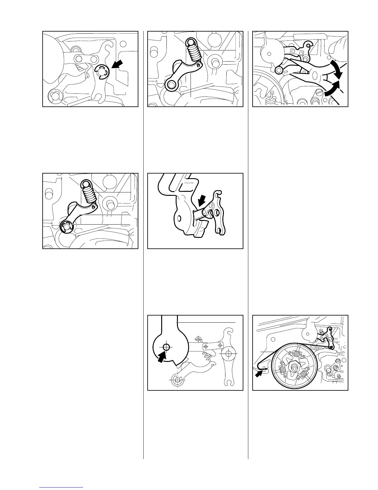
Remove the E-clip from the pivot
pin.
– Pull the hand guard and lever
from the pivot pins.
VA
138RA009
– Pull the lever out of the hand
guard.
Remove the E-clip (3) from pivot
pin of lever (2) and detach the
spring (1).
Remove the cam lever and
VA
138RA010
1
2
3
spring.
– Clean all disassembled parts in
white spirit. Replace any worn or
damaged parts.
Fit the cam lever (2) and
spring (1).
– Fit the E-clip.
VA
1
2
138RA011
Insert lever in the side of the hand
guard so that short arm of lever
points up.
Note:
Check correct installed position of
lever.
VA
138RA012
Position the hand guard (1)
against the pivot pin and fit the
other side of the hand guard over
the fan housing.
VA
138RA013
1
Press the cam lever slightly
downward and push the hand
guard and lever onto the pivot
pins.
– Secure lever with E-clip.
– Insert hand guard mounting
VA
138RA014
screw with captive washer at fan
side and tighten down firmly (see
"Tightening Torques")
Important:
Coat all sliding and bearing points
with STIHL multipurpose grease,
see 13.2, or (better) with
molybdenum grease (e.g.
Molykote), see 13.2.
Do not lubricate the brake band.
First attach the brake band (1) to
the lever (2) and then push it into
the crankcase recess (arrow).
VA
138RA007
1
2
4.4.2 Installing
 Loading...